Basic application
In this section, you will implement a simple control strategy for the mass-spring-damper system using MARTe2 components. The control strategy will be based on a PID controller that adjusts the external force (\(F\)) applied to the mass based on the error between the desired position and the actual position of the mass.

Schematic representation of the mass-spring-damper system control system.
The first step is to identify the main components required for the control of the mass-spring-damper system and map them to existing MARTe2 components. The main components are:
Desired position: This component represents the target position for the mass.
Controller: This component implements the control logic that calculates the external force (\(F\)) based on the error between the desired position and the actual position of the mass.
Mass-spring: This component represents the physical system of the mass-spring-damper and simulates its dynamics based on the applied force.
Monitoring: This component allows monitoring the system’s behaviour, such as the actual position of the mass and the applied force.
The following parameters are common to all the examples in this tutorial:
Mass (\(m\)): 1 kg
Damping coefficient (\(c\)): 0.5 Ns/m
Spring stiffness (\(k\)): 10 N/m
Initial position of the mass: 0 m
Initial velocity of the mass: 0 m/s
Sampling time: 0.01 s
In this example, the system will be controlled to maintain a constant position. The desired position will be set to a fixed value, and the controller will adjust the force to keep the mass at that position.
Application architecture
The selected components are:
Desired position: ConstantGAM
Default. 1 +GAMReference = {
2 Class = ConstantGAM
3 OutputSignals = {
4 ReferencePosition = {
5 DataSource = DDB1
6 Type = float64
7 Default = 2.0
8 }
9 }
10 }
Controller: PIDGAM. The controller takes as input the desired position (ReferencePosition) and the actual position of the mass (Position) and produces as output the control force (Force).
 1        +GAMController = {
 2            Class = PIDGAM
 3            Kp = 22.0
 4            Ki = 40.0
 5            Kd = 12.3
 6
 7            SampleTime = 0.01
 8            MaxOutput = 30
 9            MinOutput = -30
10            InputSignals = {
11                ReferencePosition = {
12                    DataSource = DDB1
13                    Type = float64
14                    NumberOfDimensions = 1
15                    NumberOfElements = 1
16                }
17                Position = {
18                    DataSource = DDB1
19                    Type = float64
20                    NumberOfDimensions = 1
21                    NumberOfElements = 1
22                }
23            }
24            OutputSignals = {
25                Force = {
26                    DataSource = DDB1
27                    Type = float64
28                    NumberOfDimensions = 1
29                    NumberOfElements = 1
30                }
31            }
32        }
Mass-spring: SSMGAM. The SSMGAM implements the spring-mass-damper system dynamics using a state-space representation. The input is the control force (Force) and the outputs are the position (Position) and velocity (Velocity) of the mass, as well as the internal states (not used in this application).
 1        +GAMSpringMass = {
 2            Class = SSMGAM
 3            StateMatrix = {{0.99950137122912 0.009972575417601597} {-0.09972575417601597 0.9945150835203193}}
 4            InputMatrix = {{4.9862877088007974e-05} {0.009972575417601595}}
 5            OutputMatrix = {{1.0 0.0} {0.0 1.0}}
 6            FeedthroughMatrix = {{0.0} {0.0}}
 7
 8            ResetInEachState = 1
 9            InputSignals = {
10                Force = {
11                    DataSource = DDB1
12                    Type = float64
13                }
14            }
15            OutputSignals = {
16                Position = {
17                    DataSource = DDB1
18                    Type = float64
19                }
20                Velocity = {
21                    DataSource = DDB1
22                    Type = float64
23                }
24                StatePosition = {
25                    DataSource = DDB1
26                    Type = float64
27                }
28                StateVelocity = {
29                    DataSource = DDB1
30                    Type = float64
31                }
32            }
33        }
Monitoring: LoggerDataSource to log all the signals.
GAMTimer: IOGAM. Triggers the execution of the thread at a fixed rate of 100 Hz, which corresponds to the sampling time of 0.01 s.
 1        +GAMTimer = {
 2            Class = IOGAM
 3            InputSignals = {
 4                Counter = {
 5                    DataSource = Timer
 6                    Type = uint32
 7                }
 8                Time = {
 9                    Frequency = 100
10                    DataSource = Timer
11                    Type = uint32
12                }
13            }
14            OutputSignals = {
15                Counter = {
16                    DataSource = DDB1
17                    Type = uint32
18                }
19                Time = {
20                    DataSource = DDB1
21                    Type = uint32
22                }
23            }
24        }
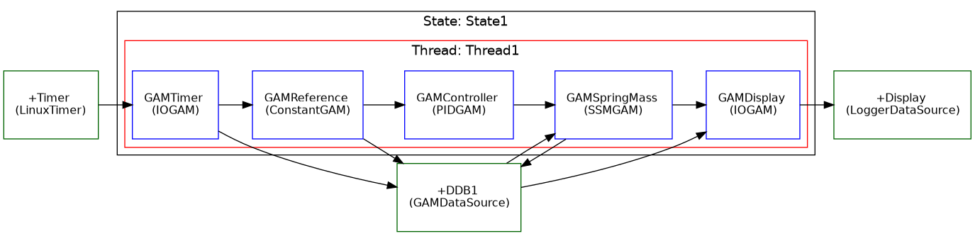
Schematic representation of the mass-spring-damper system MARTe2 configuration.
Note
The Position signal provided to the Controller GAM is connected to the Position output of the MassSpring GAM. Due to the execution semantics of MARTe2, this value corresponds to the output computed during the previous time step.
As a result, the controller effectively operates on the delayed signal \(\text{Position}[k-1]\), introducing an implicit unit delay \(z^{-1}\) in the feedback path.
This scheme is commonly used in MARTe2 configurations. By default, the initial value of the delayed signal is set to zero; however, it can be explicitly initialised using the Default parameter of the signal.
Running the application
Start the application with:
./MARTeApp.sh -f ../Configurations/MassSpring/RTApp-MassSpring-1.cfg -l RealTimeLoader -s State1
Once the application is running, inspect the screen output and verify that the log shows the Position signal converging to the desired reference position (which is set to 2 m in this example):
$ [Information - LoggerBroker.cpp:152]: Time [0:0]:28890000
$ [Information - LoggerBroker.cpp:152]: ReferencePosition [0:0]:2.000000
$ [Information - LoggerBroker.cpp:152]: Position [0:0]:2.000000
$ [Information - LoggerBroker.cpp:152]: Velocity [0:0]:0
$ [Information - LoggerBroker.cpp:152]: Force [0:0]:20.000000

 ...
Exercises
Ex. 1: Modify the reference position
Edit the file
../Configurations/MassSpring/RTApp-MassSpring-2.cfgand modify the ReferencePosition to3.1m.Verify the output of the Position in the logger.
Why does the Position not converge to the new reference position?
./MARTeApp.sh -f ../Configurations/MassSpring/RTApp-MassSpring-2.cfg -l RealTimeLoader -s State1
Solution
The solution is to modify the Default property of the signal in the ConstantGAM output.
 1        +GAMReference = {
 2            Class = ConstantGAM
 3            OutputSignals = {
 4                ReferencePosition = {
 5                    DataSource = DDB1
 6                    Type = float64
 7                    Default = 3.1
 8                }
 9            }
10        }
The reason why the Position does not converge to the new reference position is that the output of the controller is limited to 30 N. Modify this parameter to e.g. 40 N in the PIDGAM configuration to allow the controller to apply a larger force and reach the new reference position.
 1        +GAMController = {
 2            Class = PIDGAM
 3            Kp = 22.0
 4            Ki = 40.0
 5            Kd = 12.3
 6
 7            SampleTime = 0.01
 8            MaxOutput = 40
 9            MinOutput = -30
10            InputSignals = {