HotRIO F-HEE-PIR (Piranha)
Datasheet for this product available here
The HotRIO F-HEC-PIR board (codename Piranha) is a HotRIO controller board developed by Fusion for Energy (F4E). It can function either as an independent HotRIO node, communicating with the rest of the system via the HotRIO protocol, or as an expansion board, operating under the control of another HotRIO node.
Key features
HotRIO controller board solution for Eurocard-mounted systems.
HotRIO-node capable hardware.
Features 4 SFP communication interfaces.
Dual-role board, may be used as Eurocard-chassis master or expansion-board.
Technical Specifications
Form factor |
160 x 100 mm Eurocard board |
FPGA |
LFE5UM5G-85F |
Backplane slot |
240-pin Type A slot |
FPGA interfaces |
64 × LVDS pairs, 27 × LVTTL lines |
Communication interfaces |
4 × SFP modules (up to 1 Gbps each) |
Clock inputs |
50 MHz internal oscillator, 10 MHz external clock via SMB |
Time sync |
1 × external PPS signal via SMB |
Power supply |
5 V DC through Backplane connector or USB |
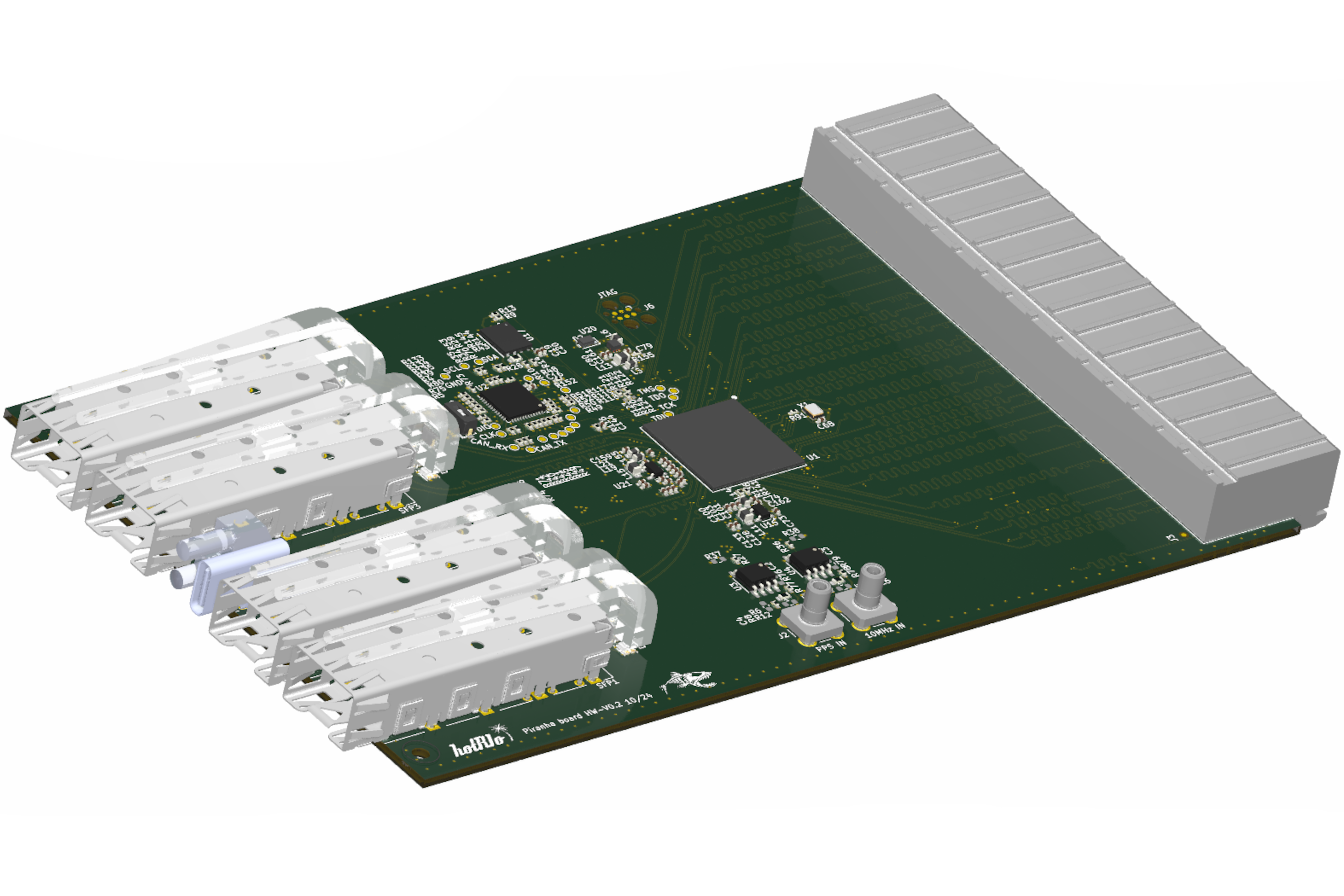
At its core, the F-HEC-PIR board features a Lattice ECP5 FPGA, which handles all HotRIO protocol communication, manages expansion boards when connected, and performs the necessary signal acquisition and processing. To enable high-speed connectivity, the board includes four 1Gbps SFP fiber optic ports, allowing it to interface with other HotRIO nodes, general-purpose network equipment, or custom communication protocols using standard fiber optic cabling.
Because the board relies solely on high-speed fiber optic communication interfaces, aside from its expansion board connection, it is specifically designed as a communication node. This makes it an ideal solution not only for HotRIO systems but also for external applications requiring high-bandwidth fiber optic data transmission at speeds of up to 1Gbps. For use cases that involve low-speed or non-serialized fiber optic signals, it is recommended to use dedicated fiber optic I/O expansion boards.
This board is designed to be used in each HotRIO Eurocard chassis, serving as the chassis master or controller. The mounting solution is optimized to leverage the FPGA on the Piranha board as the main processor of the chassis, handling I/O operations, computation, and communication via the HotRIO protocol, as well as other supported protocols. In this architecture, the Piranha board forms the core of the Eurocard chassis solution.
When used as an expansion board, it enables high-speed I/O via fiber optics through its SFP interfaces, effectively transforming the Piranha base into a high- performance I/O module with onboard processing capabilities.
Detailed description
Board Overview
The F-HEC-PIR is a high-performance HotRIO Eurocard controller board developed by Fusion For Energy, purpose-built to deliver robust HotRIO communication and advanced local data processing capabilities within Eurocard chassis systems. At its core is a Lattice ECP5 FPGA, which interfaces directly with four SFP cages, each supporting SFP modules capable of data rates up to 1Gbps. This architecture enables the board to simultaneously manage high-speed fiber optic communication across multiple channels, supporting a wide range of protocols—including the HotRIO protocol and other custom or standard network protocols as required by the application.
The FPGA orchestrates the seamless transfer of data between the Eurocard backplane I/O and the SFP ports, ensuring efficient, low-latency communication for both control and data acquisition tasks. This makes the F-HEC-PIR an ideal solution for applications demanding high bandwidth, flexible connectivity, and real-time processing within modular Eurocard-based systems. Its design allows it to function either as the central controller (chassis master) or as a high-performance expansion module, adapting to diverse system architectures and requirements.
This board can operate in multiple roles (only one at a time), depending on its connection to the HotRIO Type A Eurocard backplane:
Backplane Master Role: When installed in the master slot of the HotRIO Type A Eurocard backplane, the board utilizes all 240 pins of the backplane connector. In this configuration, the FPGA can access all available backplane lanes, allowing it to manage and communicate with up to four expansion boards connected to the remaining slots. This role positions the F-HEC-PIR as the main controller of the Eurocard chassis, orchestrating data flow and system coordination.
Expansion Board Role: When installed in an expansion slot, only 60 of the 240 pins are connected. In this mode, the board functions as an expansion module, relinquishing control over other expansion boards. Despite this, it retains its high-speed I/O and onboard processing capabilities, making it a powerful and flexible expansion solution for demanding applications.
FPGA
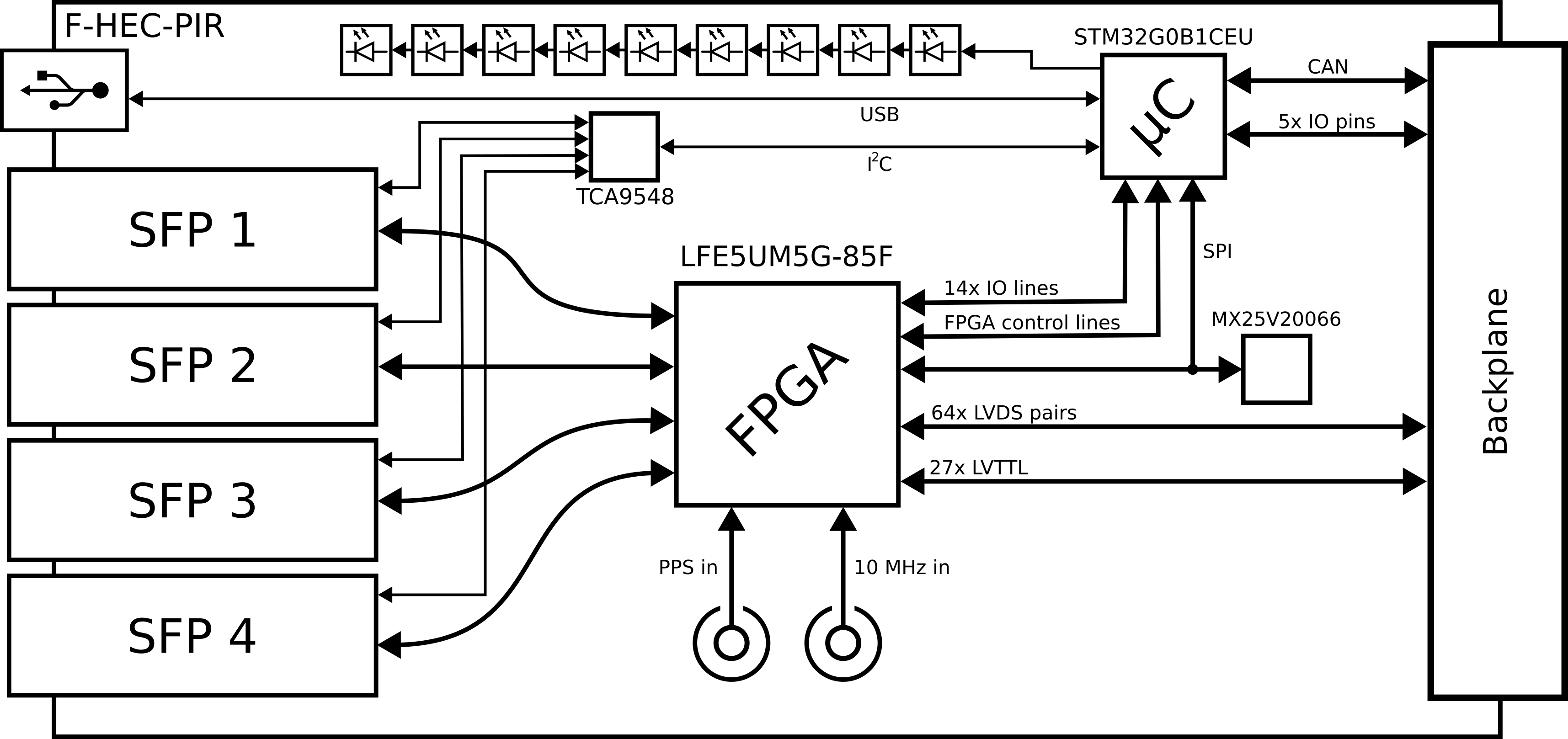
The HotRIO F-HEC-PIR board is equipped with a Lattice Semiconductor LFE5UM5G-85F FPGA, which serves as the central processing and communication hub for the board.
The FPGA interfaces directly with four SFP cages (numbered 1 through 4), each connected via dedicated LVDS TX and RX pairs to the FPGA’s SERDES blocks. This configuration supports data rates up to 1Gbps per SFP, utilizing 8b/10b encoding for robust high-speed communication. These SFP interfaces enable the board to connect to other HotRIO nodes, network equipment, or custom fiber optic links.
In addition to the SFP interfaces, the FPGA is connected to two SMB coaxial connectors on the board. One provides an external clock input (nominally 10MHz), and the other supplies an external PPS (Pulse Per Second) signal for precise time synchronization. Both signals are routed through NB3L553DG clock fanout buffers to ensure signal integrity before reaching the FPGA. This setup allows multiple HotRIO boards to operate synchronously, sharing a common clock and timing reference.
For standalone or fallback operation, the board includes a 50MHz crystal oscillator directly connected to the FPGA. This oscillator ensures a stable and reliable clock source for the FPGA, supporting backup, recovery, and management operations even if external timing signals are unavailable.
The F-HEC-PIR features a 240-pin backplane connector, enabling full integration with the Eurocard chassis. This connector routes 64 LVDS pairs and 27 LVTTL lines from the FPGA to the backplane, providing high-bandwidth, low-latency communication channels for interfacing with other boards and system components. This extensive connectivity allows the F-HEC-PIR to serve as either the central controller or a high-performance expansion module within the HotRIO Eurocard ecosystem.
Manager microcontroller
The F-HEC-PIR board integrates a STM32G0B1CE microcontroller, which serves as the board manager, handling essential management and supervisory functions. The main responsibilities of the manager microcontroller include:
FPGA firmware management and configuration: The microcontroller oversees the loading and configuration of the FPGA firmware. It manages the SPI interface to the FPGA, orchestrating the transfer of the bitstream stored in external flash memory (MX25V20066) to the FPGA during boot. Additionally, the microcontroller can store and retrieve configuration files in the flash memory, enabling dynamic reconfiguration of the FPGA by writing to its internal registers via SPI.
CAN bus communication: The microcontroller connects to the CAN bus available on the HotRIO Type A Eurocard backplane, facilitating communication with other board managers in the system. When the F-HEC-PIR operates as a backplane master, the microcontroller coordinates management traffic, relays serial communications as needed, and verifies the presence and configuration of expansion boards to ensure compatibility with the intended FPGA firmware. In expansion board mode, it participates as a CAN node, providing management access but not controlling the bus.
SFP module monitoring and diagnostics: Through an I2C interface, the microcontroller monitors the SFP modules installed in the board’s four cages. It detects module presence, reads diagnostic information, and accesses the internal memory map of each SFP to determine module type, operational parameters, and fault conditions.
System status reporting: The microcontroller provides real-time status updates for the FPGA and other subsystems. It communicates status via serial interfaces (USB or sideband) and visually through 10 onboard serially-driven RGB LEDs, enabling users to quickly diagnose and debug board operation.
External Memory and SPI Bus Architecture
The STM32G0B1CE manager microcontroller is paired with a MX25V20066 SPI flash memory, which stores both the FPGA firmware bitstream and a dedicated partition for microcontroller configuration files. The SPI bus is shared among the microcontroller, the FPGA, and the external flash memory, with bus mastership dynamically assigned based on the operational phase:
Normal operation: The microcontroller acts as the SPI master, while the FPGA and flash memory function as slaves. This allows the microcontroller to access the FPGA’s register map and manage the contents of the external flash.
FPGA boot sequence: During FPGA configuration, the FPGA temporarily assumes the SPI master role to directly access the flash memory and load its bitstream. The microcontroller tri-states its SPI lines during this phase to avoid bus contention. Once configuration is complete, mastership reverts to the microcontroller.
This flexible SPI architecture ensures reliable firmware loading, robust configuration management, and seamless coordination between the microcontroller and FPGA throughout all operational states.
SFPs and I2C Bus Architecture
The F-HEC-PIR board is equipped with four SFP cages, each capable of accepting standard SFP networking modules that interface directly with the FPGA for high-speed data transmission. In addition to the high-speed data lines, each SFP module provides a low-speed I2C interface, which is accessible by the manager microcontroller for monitoring and configuration purposes. This I2C interface allows the microcontroller to read diagnostic information, configure operational parameters, and monitor the status of each SFP module, which is essential for system management and troubleshooting.
According to the SFF-8472 standard, each SFP module implements two fixed I2C device addresses: 0xA0 and 0xA2. The 0xA0 address is used for accessing the module’s serial EEPROM, which contains identification, vendor, and configuration data. The 0xA2 address is reserved for accessing diagnostic monitoring interface (DMI) data, such as temperature, voltage, bias current, and optical power levels. Since these addresses are fixed and identical for all SFP modules, connecting multiple SFPs to the same I2C bus would result in address conflicts.
To resolve this, the F-HEC-PIR board incorporates a TCA9548 I2C switch IC. The TCA9548 is an 8-channel I2C multiplexer that allows the microcontroller to select which SFP module is connected to the I2C bus at any given time. The microcontroller communicates with the TCA9548 at its unique I2C address and configures it to enable one of its downstream channels, thereby connecting the I2C bus to a specific SFP module. This approach ensures that, despite all SFP modules sharing the same internal I2C addresses, only one module is accessible on the bus at a time, preventing address collisions and enabling reliable communication.
In operation, the microcontroller sequentially selects each SFP channel via the TCA9548, performs the required read or write operations at addresses 0xA0 and 0xA2, and then moves to the next module as needed. This architecture provides robust and scalable management of multiple SFP modules, supporting advanced diagnostics and configuration capabilities for each port independently.
USB Connection
The manager microcontroller is equipped with a standard USB Type-C receptacle located on the front panel of the board. This USB interface connects directly to the manager microcontroller and provides management access via a serial command-line interface (CLI), which is exposed as a USB-CDC virtual serial port. The USB connection is intended exclusively for board management, configuration, and diagnostics; it is not designed for high-speed data transfer or application-level communication.
It is important to note that the USB interface is not connected to the FPGA and therefore cannot be used for direct FPGA programming or high-bandwidth data streaming. The USB port is compliant with the USB 2.0 standard, supporting only Full-Speed (12 Mbps) operation. As such, it is suitable for tasks such as firmware updates, board configuration, status monitoring, and diagnostic access, but not for high-speed data acquisition or real-time communication with the FPGA.
Light Indicators
The F-HEC-PIR board is equipped with a total of 10 addressable RGB LEDs, all controlled by the manager microcontroller via a serial interface. These LEDs provide clear, real-time visual feedback on the operational status of the board and its subsystems. Specifically, each SFP module is associated with two dedicated LEDs, enabling per-port status indication such as link activity, fault conditions, or module presence. The remaining two LEDs are reserved for displaying the overall board status, including power, initialization, or error states. This flexible LED arrangement allows users and technicians to quickly assess board health and activity at a glance, streamlining diagnostics and system monitoring.
CAN Bus
The F-HEC-PIR board is equipped with CAN bus capabilities to facilitate communication between all boards connected to the Eurocard backplane. In master mode, the board’s manager microcontroller coordinates management traffic and communicates with expansion boards. When operating as an expansion board, it provides CAN access for management and diagnostics, but does not control the bus.
The microcontroller supports both CAN 2.0 and Flexible Data-rate CAN (FDCAN), with data rates up to 8 Mbit/s during the data phase. Notably, the CAN transceiver is not integrated on the F-HEC-PIR board itself; instead, it is provided on the backplane. This design minimizes the length of CAN bus stubs, improving signal integrity and reducing noise by keeping the transceiver close to the main bus lines.
The HotRIO Type A Eurocard backplane is equipped with CAN transceivers featuring enable/disable (isolation) capabilities. This allows the controller board installed in the master slot to selectively enable or disable CAN connectivity for each slot. Such control is leveraged for several advanced features:
Software updates: The master board can isolate and update the firmware of expansion board manager microcontrollers over the CAN bus, ensuring reliable and targeted updates.
Slot-based addressing: During system initialization, the master assigns a unique CAN base address to each expansion board based on its physical slot location, enabling automatic board indexing and streamlined communication.
Bus arbitration and diagnostics: By selectively enabling CAN transceivers, the master can perform diagnostics, isolate faulty boards, and manage bus arbitration to maintain system reliability.
When the F-HEC-PIR board operates as the backplane master, the FPGA provides dedicated I/O lines to control the enable signals of the CAN transceivers on the backplane. This architecture ensures robust, flexible, and scalable CAN communication across all boards in the Eurocard chassis.
Interfaces
This section provides an overview of the main interfaces available on the F-HEC-PIR board. Each interface is briefly described, including its function and intended use. For most interfaces, a mechanical diagram is provided to indicate their physical location on the board. The 240-pin Eurocard backplane connector is described in detail, including its full pinout.
SFP Cages (4x): The board features four SFP (Small Form-factor Pluggable) cages, each supporting standard SFP modules for high-speed fiber optic communication. These interfaces are directly connected to the FPGA, enabling data rates up to 1 Gbps per port. The SFP cages are located along the front edge of the board for easy access and hot-swapping. Each SFP port also provides a low-speed I2C interface for module monitoring and diagnostics, managed by the onboard microcontroller.
SMB Coaxial Connectors (2x): Two SMB coaxial connectors are provided for external timing and synchronization signals:
Clock Input: Accepts an external reference clock (nominally 10 MHz) for precise timing.
PPS Input: Accepts an external Pulse Per Second (PPS) signal for time synchronization.
Both signals are routed to the FPGA via clock fanout buffers. The SMB connectors are located on the front panel for convenient access.
Management USB Type-C: A standard USB Type-C connector is available on the front panel, providing a management interface to the onboard microcontroller. This port is used for board configuration, firmware updates, diagnostics, and status monitoring via a USB-CDC virtual serial port. It is not intended for high-speed data transfer or direct FPGA programming.
240-pin Eurocard Backplane Connector: The primary interface to the Eurocard chassis is a 240-pin backplane connector, which provides power, high-speed LVDS pairs, LVTTL signals, CAN bus lines, and control signals between the F-HEC-PIR board and the rest of the system. This connector enables the board to function as either a chassis master or an expansion module, depending on its slot position.
Backplane Connector Pinout: The following table details the pinout of the 240-pin Eurocard backplane connector. Each pin is assigned a specific function, supporting high-speed data transfer, control, and power distribution. For a complete description of each signal, refer to the HotRIO Eurocard backplane specification.
In summary, the F-HEC-PIR board provides a comprehensive set of interfaces for high-speed communication, precise timing, system management, and robust integration within Eurocard-based systems. The mechanical diagrams above indicate the physical location of each interface, while the detailed pinout ensures correct system-level connectivity.