HotRIO F-HEE-FIO-3I3O
Datasheet for this product available here
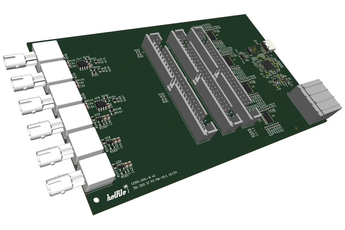
The HotRIO F-HEE-FIO-3I3O is a fiber optic I/O expansion board in Eurocard format, developed by F4E for the HotRIO system. It is designed to enable any controller board installed in a HotRIO Eurocard chassis to interface with up to three fiber optic input channels and three fiber optic output channels per backplane slot.
Key features
HotRIO solution for fiber optic interfaces
Designed for Eurocard mounted solutions
3 input and 3 output simultaneous fiber channels
No onboard processing, only electrical-to-fiber adapter
Technical Specifications
Form factor |
100x160 mm (Eurocard) |
Mounting |
Eurocard chassis |
Backplane interface |
HotRIO PCIe |
Fiber optic channels |
3x input, 3x output |
Transceivers |
Avago HFBR-1412Z |
Receivers |
Avago HFBR-2412Z |
Optical wavelength |
850 nm MMF |
Connector type |
ST (Straight Tip) |
Fiber optic compatibility |
50/120 um, 62.5/125 um, 100/140 um or 200 um at 850nm |
Optical bandwidth |
Up to 160 MBd |
Power supply |
5V DC (from backplane) |
Power consumption |
TBD W |
This board integrates three optical transmitters (HFBR-1412Z) and three optical receivers (HFBR-2412Z), supporting ST-type fiber connectors and optimized for use with 850 nm multimode fiber. These components serve as front-end adapters that convert electrical signals to optical signals and vice versa, enabling optical communication lines to be interfaced directly with the system FPGA. All signal processing is performed by the controller board’s FPGA—this board solely provides the physical interface for optical connectivity.
The F-HEE-FIO-3I3O connects directly to the HotRIO backplane and is intended for use with controller boards such as the F-HEE-PIR. It does not include any programmable logic devices; instead, it incorporates a management microcontroller used solely for identification and status monitoring via the CAN bus, allowing the board to be properly recognized within the chassis.
Each optical transceiver channel interfaces with the controller board’s FPGA via LVTTL-level digital lines, routed through level shifters to ensure voltage compatibility and signal integrity. Additionally, unused digital pins from the backplane connector are routed—via appropriate level shifting stages—to the footprint of an unpopulated header.
Detailed description
Board Overview
The F-HEE-FIO-3I3O is a HotRIO Eurocard expansion board developed by Fusion For Energy, designed to provide seamless fiber optic interfacing capabilities for HotRIO controller boards. It features three fiber optic transmitters and three fiber optic receivers, which can be directly connected to a Eurocard-compatible HotRIO controller board. The board acts exclusively as a physical interface, converting LVTTL signals from the controller board’s FPGA to the voltage levels required by the fiber optic transceivers and receivers, without introducing any onboard signal processing.
The main objective of this board is to enable direct interfacing with fiber optic signals within HotRIO Eurocard chassis solutions, leveraging the controller board’s FPGA for all signal processing tasks. The F-HEE-FIO-3I3O ensures compliance with voltage and management requirements common to all HotRIO Eurocard series products, integrating several subsystems to support reliable operation.
A simplified schematic of the onboard circuits is shown below:
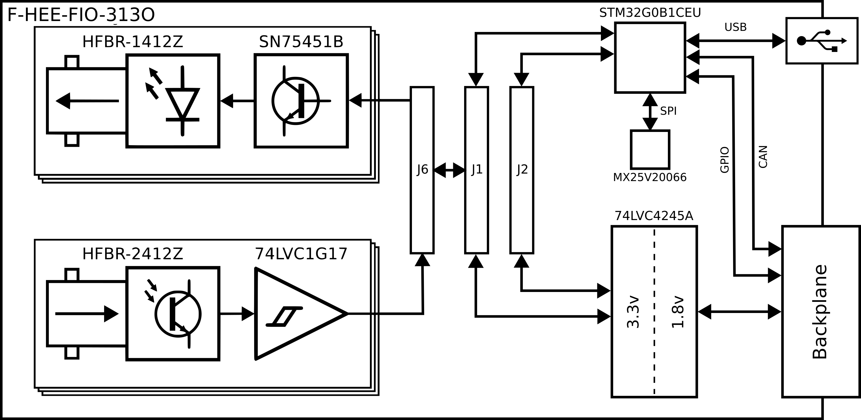
As illustrated, the data paths between the controller board and the optical transceivers are routed through a 74LVC4245A voltage level converter. This device provides bidirectional level shifting between 1.8V (Eurocard chassis side) and 3.3V (transceiver/receiver side), allowing the controller board to operate at lower voltages for reduced power consumption and improved noise immunity.
In addition to the optical interface, the board includes a management subsystem based on an STM32G0B1CEU microcontroller and an MX25V20066 external EEPROM. The microcontroller is responsible for board identification, status monitoring, and communication with the controller board via the CAN bus, ensuring proper integration within the HotRIO chassis. The EEPROM provides non-volatile storage for configuration data.
The board also offers three expansion connectors (J1, J2 and J1001), implemented as 2x25 2.54mm pitch headers. These connectors provide access to all unused pins from the backplane, routed through the voltage level converter, and some are also connected to unused microcontroller pins. This design enables developers to prototype custom solutions or interface additional I/Os as needed.
Optical Transceivers and Receivers
The F-HEE-FIO-3I3O features three HFBR-1412Z optical transmitters and three HFBR-2412Z optical receivers, each independently interfaced with the controller board’s FPGA. Each optical channel is routed through a voltage level converter to ensure compatibility with the controller board’s logic levels, maintaining signal integrity and reliable operation across all channels.
The signal conditioning circuitry for the transmitters and receivers is specifically designed to maximize performance and reliability:
Transmitters: The HFBR-1412Z optical transmitters are driven by SN75451B high-speed drivers, which are placed between the voltage level shifter (connected to the FPGA) and the transmitter inputs. These drivers provide the necessary current drive and fast switching characteristics required by the optical transmitters, ensuring robust operation at high data rates. This approach prevents signal degradation that could occur if the FPGA or level shifter were to drive the transceivers directly, particularly over longer PCB traces or in the presence of capacitive loading.
Receivers: The HFBR-2412Z optical receivers output signals that are first conditioned by a 74LVC1G17 Schmitt trigger buffer before being passed to the voltage level shifter. The Schmitt trigger cleans up slow or noisy signal edges from the optical receiver, converting them into sharp, well-defined digital transitions. This improves noise immunity and ensures that the voltage level shifter receives clean logic signals, which is critical for reliable detection by the FPGA, especially in electrically noisy environments or when dealing with marginal optical signals.
All these fiber optic ports utilize ST (Straight Tip) connectors and are optimized for multimode fiber operation at 850 nm. Supported fiber types include:
50/120 um
62.5/125 um
100/140 um
200 um
Together, these design choices ensure that the F-HEE-FIO-3I3O provides a robust and reliable fiber optic interface, capable of maintaining high signal integrity and supporting demanding industrial applications.
Management Microcontroller
A key subsystem of the F-HEE-FIO-3I3O is its onboard STM32G0B1CEU6 microcontroller, which serves as the intelligent management interface for the board. This 32-bit ARM Cortex-M0+ microcontroller is responsible for:
Board identification, including automatic detection by the controller board during initialization.
Health and status monitoring, such as reporting thermal, voltage, or fault conditions via CAN.
Configuration exchange with the controller board through a dedicated CAN bus interface, ensuring full compliance with the HotRIO communication protocol stack.
The microcontroller is connected to an MX25V20066 external EEPROM via SPI, providing non-volatile storage for board-specific configuration data, including ID, versioning, and user-defined metadata.
In addition to its communication and monitoring roles, the microcontroller exposes several general-purpose I/O (GPIO) pins. These are used for interrupt signaling, diagnostics, or auxiliary communication with the controller board. Unused microcontroller I/Os are routed to the J1, J2 and J1001 expansion headers, allowing developers to extend the board’s functionality for prototyping or specialized applications. This modular design supports future firmware updates, in-field diagnostics, and hardware extensions without requiring redesign of the base board.
Interfaces
The F-HEE-FIO-3I3O HotRIO expansion board provides a comprehensive set of interfaces, enabling flexible integration within Eurocard-based systems. The main interfaces are described below:
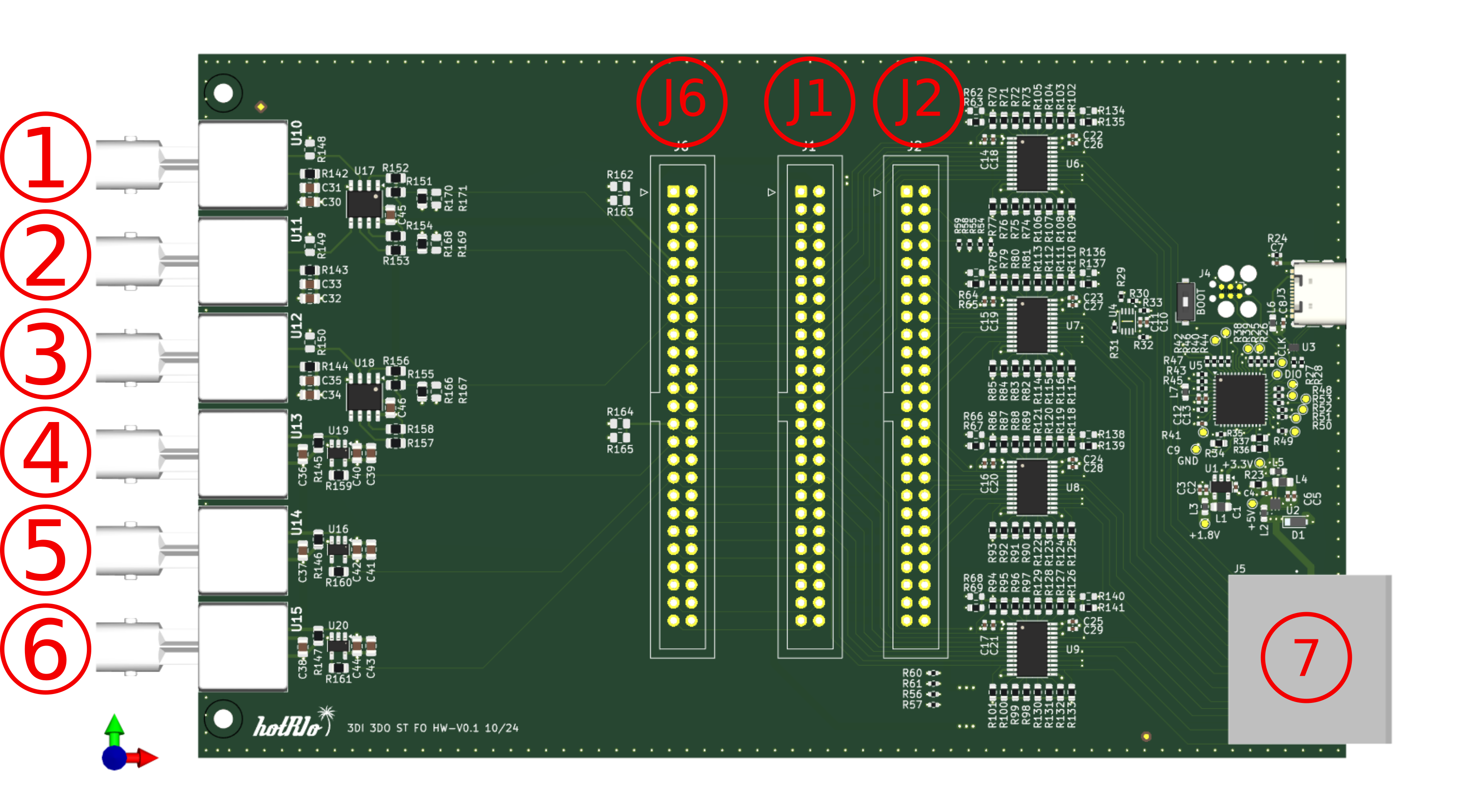
Fiber Optic Ports: Six ST-type fiber optic connectors are provided—three for input (connected to optical receivers) and three for output (connected to optical transmitters). These ports support multimode fiber operation at 850~nm and are directly interfaced with the controller board’s FPGA via level shifters and signal conditioning circuits. Each channel operates independently, enabling simultaneous bidirectional optical communication. Ports labeled in the interface scheme below labeled 1-3 are transceiver ports, while ports labeled 4-6 are receiver ports.
Backplane Connector: A 98-pin 8X PCIe edge connector provides the primary electrical interface to the system. This connector routes up to 16 LVTTL digital lines (originating from the controller board’s FPGA) to the fiber optic transceivers and receivers. It also carries the CAN bus for management communication with the onboard microcontroller, as well as additional I/O lines for board identification, status, and expansion. Unused digital lines from the backplane are routed to the J1, J2 and J1001 expansion headers for user access. This connector is labeled as 7 in the interface scheme below
Expansion Headers (J1, J2, and J1001): Three 2 x 25 pin (2.54~mm pitch) headers—J1, J2, and J1001—provide flexible access to unused digital I/O lines from the backplane connector as well as spare GPIOs from the onboard microcontroller. These headers are designed to facilitate prototyping, debugging, and hardware expansion without requiring modifications to the base board. J1 and J1001 are routed in a mirrored configuration, allowing developers to connect to the same set of signals from either the top or bottom side of the board for convenience. All signals interfacing with the onboard transceivers and receivers are also accessible via J1 and J1001, enabling direct probing and debugging of optical I/O channels. J2 provides additional access to unused microcontroller pins and other auxiliary signals. For clarity, all signal names on these headers correspond to their original backplane designations after passing through the voltage level converter. Detailed pinout diagrams and assignment tables are provided in the following sections to assist with development and integration.
USB Management Port: A micro-USB connector is directly connected to the STM32G0B1CEU6 microcontroller. This port is intended for board configuration, firmware flashing, diagnostics, and factory testing. It can also provide power to the microcontroller subsystem during development. The USB port is located at the rear edge of the board and is typically inaccessible during normal operation, as standard configuration and management are performed via the CAN bus interface.
CAN Bus Interface: The CAN bus is routed from the backplane connector to the onboard microcontroller, enabling robust communication for board identification, health monitoring, and configuration exchange with the controller board. This interface supports HotRIO protocol extensions for seamless integration within the chassis.
Power Supply: The board is powered via the 5~V supply provided through the backplane connector. All onboard subsystems, including the optical transceivers, microcontroller, and level shifters, derive their operating voltages from this supply using local regulation and filtering.
These interfaces collectively ensure that the F-HEE-FIO-3I3O can be easily integrated into a wide range of HotRIO Eurocard systems, supporting both standard operation and advanced prototyping or expansion requirements.