RealTimeApplication
A MARTe RealTimeApplication is assembled by connecting together GAMs and DataSources.
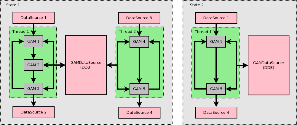
GAMs are grouped in real-time threads which are executed in the context of specific states. A RealTimeApplication shall be in one (and only one) given state at any given time.
The orchestration of the states is performed by means of messages (e.g. by a component that relays HTTP requests into MARTe messages).
Configuration
The configuration of a RealTimeApplication has to follow a set of strict rules.
In particular, the nodes Functions, Data, States and Scheduler shall exist and shall be configured using the rules defined below:
Functions
GAMs are listed inside a node named Functions of type ReferenceContainer.
$App1 = {
   Class = RealTimeApplication
   +Functions = {
      Class = ReferenceContainer
      +GAM1 = {
         Class = AGAM
         InputSignals = {
            ...
         }
         OutputSignals = {
             ...
         }
      }
      +GAM2 = {
         Class = BGAM
         InputSignals = {
            ...
         }
         OutputSignals = {
            ...
         }
      }
      ...
   }
   ...
}
GAMs can also be grouped inside reference containers (in order to improve the readability of a configuration stream) and inside GAMGroups.
$App1 = {
   Class = RealTimeApplication
   +Functions = {
      Class = ReferenceContainer
      +Controllers = {
         Class = ReferenceContainer
         +PID1 = {
            Class = PIDGAM
            InputSignals = {
               ...
            }
            OutputSignals = {
               ...
            }
         }
         +PID2 = {
            Class = PIDGAM
            InputSignals = {
               ...
            }
            OutputSignals = {
               ...
            }
         }
      }
      +GAM2 = {
         Class = GAMGroup
         +GAM3 = {
            InputSignals = {
               ...
            }
            OutputSignals = {
               ...
            }
         }
         +GAM4 = {
            InputSignals = {
               ...
            }
            OutputSignals = {
               ...
            }
         }
      ...
   }
   ...
}
Data
DataSources are grouped inside a node named Data of type ReferenceContainer.
$App1 = {
   Class = RealTimeApplication
   +Functions = {
      Class = ReferenceContainer
      ...
   }
   +Data = {
      Class = ReferenceContainer
      DefaultDataSource = DDB1
      +DDB1 = {
         Class = GAMDataSource
      }
      +LoggerDataSource = {
         Class = LoggerDataSource
      }
      +Timings = {
         Class = TimingDataSource
      }
      +Timer = {
         Class = LinuxTimer
         SleepNature = "Default"
         Signals = {
             Counter = {
                 Type = uint32
             }
             Time = {
                 Type = uint32
             }
         }
     }
     ...
   ...
}
A component of class type TimingDataSource shall exist.
The property DefaultDataSource shall define what is the DataSource to be used when the GAM signals do not specify the DataSource property.
TimingDataSource
The RealTimeApplication will automatically add to the TimingDataSource the following signals:
For every RealTimeThread, it will generate a signal named
STATE_NAME.THREAD_NAME_CycleTime, whereSTATE_NAMEis the name of the state where the thread is running andTHREAD_NAMEis the name of the RealTimeThread object instance. The type of this signal is uint32 and it holds the thread cycle time.- For every GAM, it will generate three signals named:
GAM_NAME_ReadTime,GAM_NAME_WriteTimeandGAM_NAME_ExecTimewhere GAM_NAME` is the object name of the GAM instance. The type of these signals is uint32. The
GAM_NAME_ReadTimeholds the time elapsed from the beginning of the cycle until all the input brokers for thisGAM_NAMEhave been executed;The
GAM_NAME_WriteTimeholds the time elapsed from the beginning of the cycle until all the output brokers for thisGAM_NAMEhave been executed;The
GAM_NAME_ExecTimeholds the time elapsed from the beginning of the cycle until thisGAM_NAMEhas finished its execution.
- For every GAM, it will generate three signals named:
$App1 = {
   Class = RealTimeApplication
   +Functions = {
      Class = ReferenceContainer
      +GAMDisplay = {
         Class = IOGAM
         InputSignals = {
            State1_Thread1_CycleTime = {
                Alias = State1.Thread1_CycleTime
                DataSource = Timings
                Type = uint32
            }
            GAMFixed1_ReadTime = {
                DataSource = Timings
                Type = uint32
            }
            GAMFixed1_ExecTime = {
                DataSource = Timings
                Type = uint32
            }
            GAMFixed1_WriteTime = {
                DataSource = Timings
                Type = uint32
            }
         ...
         }
       ...
       }
   ...
   }
   +Data = {
      Class = ReferenceContainer
      DefaultDataSource = DDB1
      ...
      +Timings = {
         Class = TimingDataSource
      }
      ...
Warning
Given that a MARTe object name may not contain a . and given that the cycle time signal produced by the Timings DataSource is named STATE_NAME.THREAD_NAME_CycleTime, an Alias will always have to be used to read the signal.
InputSignals = {
   State1_Thread1_CycleTime = {
      Alias = State1.Thread1_CycleTime
      DataSource = Timings
States
The available RealTimeApplication states are listed inside a node named States of type RealTimeState.
Each state shall have a node named Threads with the list of RealTimeThread components to be executed in that state.
Each RealTimeThread shall contain the name of the Functions to be executed. Note that if the function is a ReferenceContainer or a GAMGroup, the GAMs contained inside these containers shall not be declared (as they are automatically added for scheduling).
$App1 = {
   Class = RealTimeApplication
   +Functions = {
      Class = ReferenceContainer
      +Controllers1 = {
         Class = ReferenceContainer
         +PID1 = {
            ...
         }
         +PID2 = {
            ...
         }
      }
      +Controllers2 = {
         Class = ReferenceContainer
         +PID3 = {
            ...
         }
         +PID4 = {
            ...
         }
      }
      +GAMGroup1 = {
         Class = GAMGroup
         +GAM3 = {
            ...
         }
         +GAM4 = {
            ...
         }
      ...
      }
      +Reference1 = {
         Class = AGAM
         ...
      }
      +Reference2 = {
             Class = AGAM
         ...
      }
   }
   +States = {
      Class = ReferenceContainer
      +State1 = {
         Class = RealTimeState
         +Threads = {
            Class = ReferenceContainer
            +Thread1 = {
               Class = RealTimeThread
               CPUs = 0x1 //Only meaningful in operating systems that support it
               Functions = {Reference1 Controllers1 GAMGroup1} // Note that PID1 and PID2, etc are implicitly called.
            }
            +Thread2 = {
               Class = RealTimeThread
               CPUs = 0x2 //Only meaningful in operating systems that support it
               Functions = {Reference2 Controllers2}
            }
        }
     }
     +State2 = {
        Class = RealTimeState
        +Threads = {
           Class = ReferenceContainer
           +Thread1 = {
               Class = RealTimeThread
               Functions = {Reference1 GAMGroup1 }
           }
        }
Scheduler
The scheduler is defined in a node named Scheduler and the class shall inherit from GAMSchedulerI.
The name of the node containing the TimingDataSource class shall be defined in a parameter named TimingDataSource.
$App1 = {
   Class = RealTimeApplication
   ...
   +Scheduler = {
      Class = GAMScheduler
      TimingDataSource = Timings
   }
The framework offers a multi-thread scheduler (see GAMScheduler). Bare metal applications will typically develop bespoke scheduling mechanisms.
Initialisation
A RealTimeApplication is initialised just like any other MARTe Object. Internally, the RealTimeApplication initialisation is mostly delegated to the RealTimeApplicationBuilder component and is divided in two stages: first all the signals dependencies, between the GAMs and the DataSources, are completed and verified (see Rules below). This is followed by a stage where the Brokers are instantiated and all the required memory allocated.
The two states are independent and can be performed in separate phases. This allows, for example, to pre-compute (see RealTimeApplicationBuilder::ConfigureBeforeInitialisation) and directly store in the memory of a low-power embedded system the output of the signal verification logic (phase 1 of the initialisation).
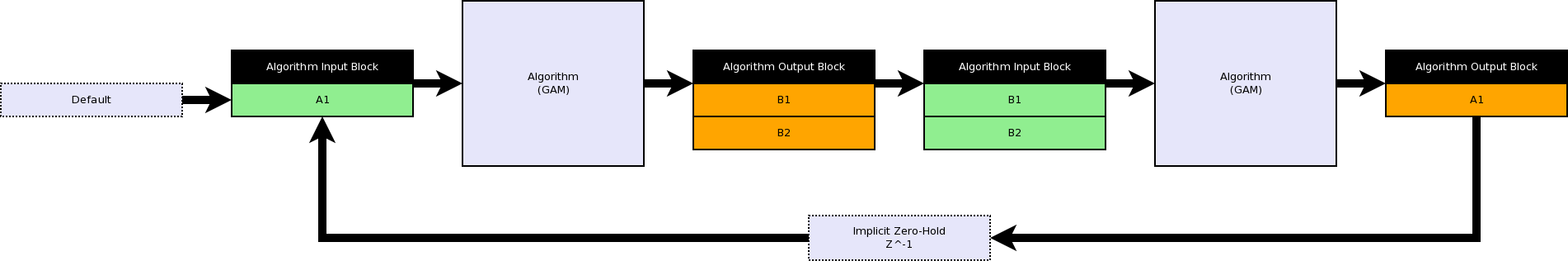
The RealTimeApplication will try to complete the missing signal properties based on the information that is available. If a GAM requires a signal that is produced by a subsequent GAM, an implicit zero-hold is introduced in the cycle and the signal is initialised to its Default value.
Rules
The following rules have to be met and are verified by the RealTimeApplication initialisation mechanism:
Global rules
The nodes
Functions,Data,StatesandSchedulershall exist;At least one GAM shall be declared;
At least one DataSource shall be declared;
Exactly one TimingDataSource shall be declared;
At least one state shall be declared;
For each state, at least one thread shall be declared;
For each thread, at least one function (GAM) shall be declared;
Signal rules
For every thread, the input port of each GAM or DataSource shall be connected to exactly one signal (from another GAM or from a DataSource);
For every thread, the output port of a given GAM or DataSource may be connected to zero or more signals (in another GAM or DataSource);
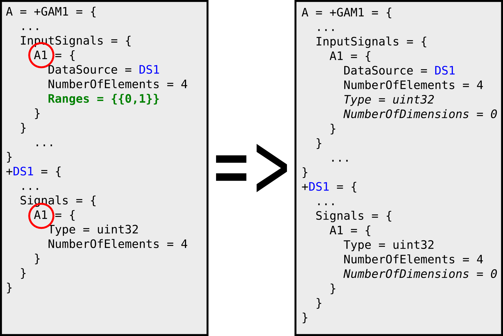
The properties (type, number of elements and number of dimensions) of each signal shall be fully consistent between the signal producer and the signal consumer;
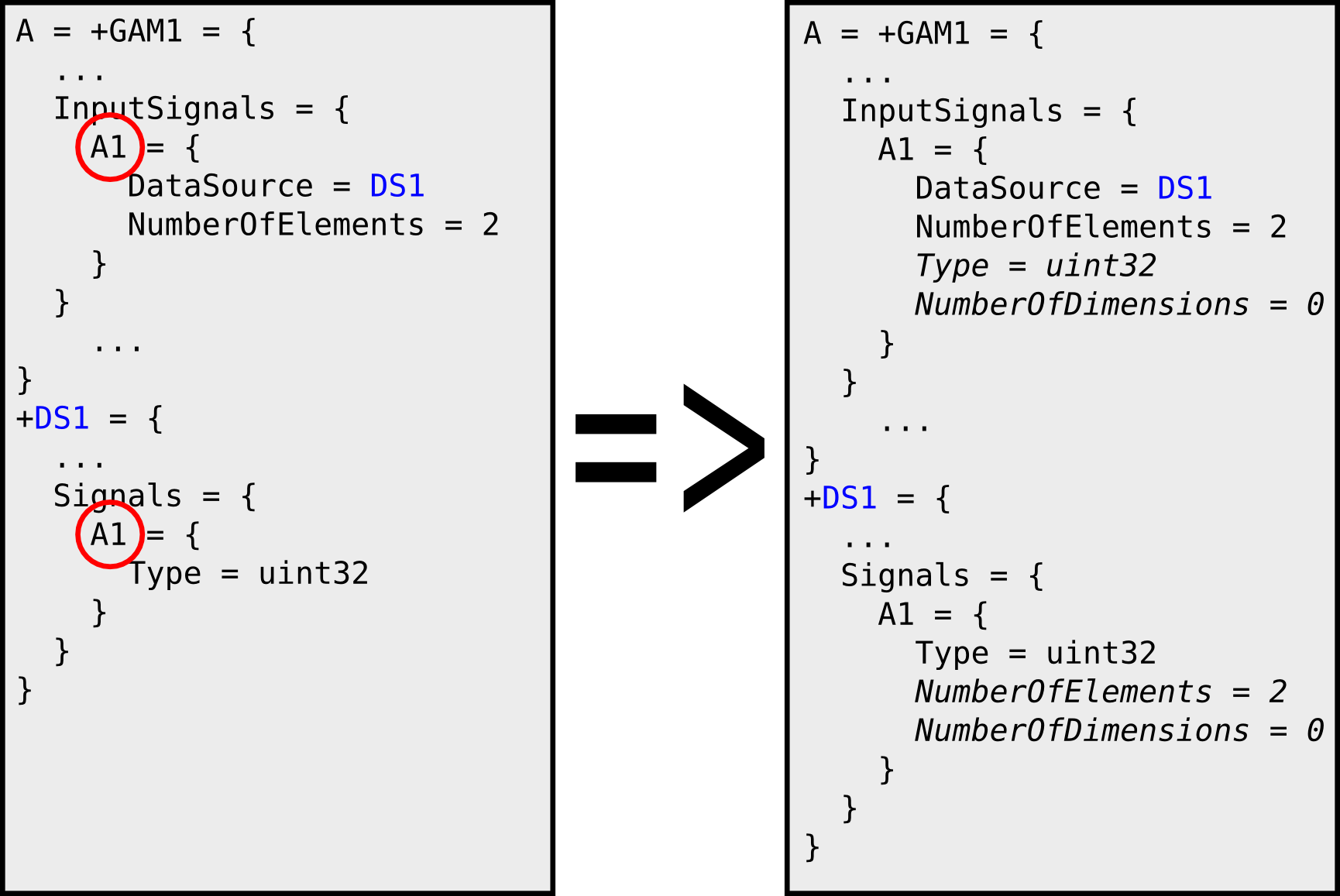
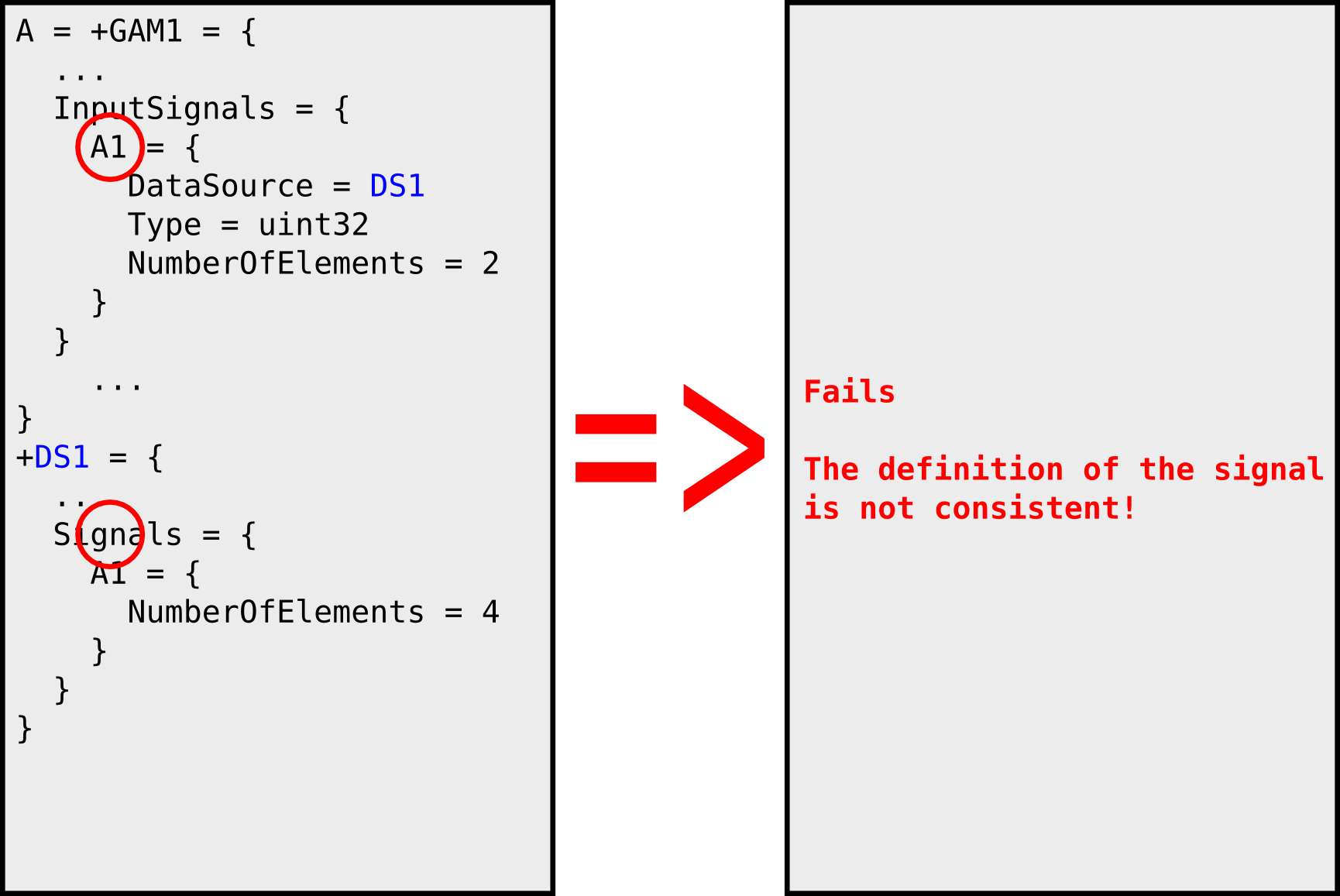
The signal type shall be defined either by the signal producer or by one of the signal consumers:
If the number of elements is not defined, one is assumed;
the number of dimensions is not defined, zero is assumed (scalar signal);
If no Default value is specified, zero is assumed.
For every thread, at most one signal shall define the property Frequency (i.e. at most one synchronisation point per thread).
The following is a valid example where the GAM resolves the signal type from the DataSource.
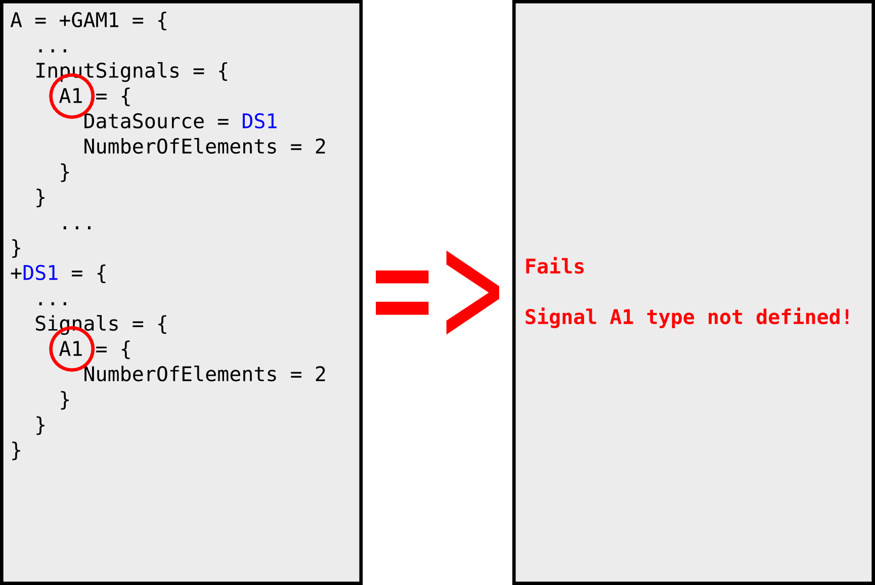
In this example the type of the signal A1 is not defined by the producer nor by the source and thus the configuration is invalid and will fail.
In the following, there is a contradiction between the properties of the signal A1 and thus the configuration will also fail.
The correct way to access an array of smaller dimensions is to use the parameter Ranges. The GAM parameter will only use (and allocate memory) to the first two elements of the array:
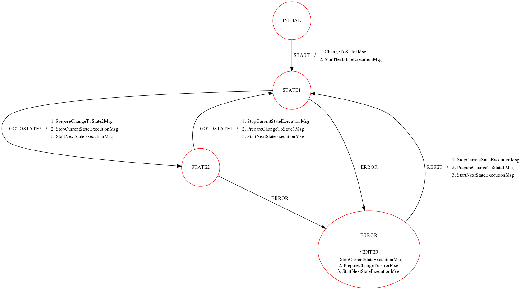
State change
The state can be changed by calling the methods PrepareNextState, StopCurrentStateExecution and StartNextStateExecution on the RealTimeApplication.
These are methods are registered as RPC functions and thus can be triggered using the messaging mechanisms.
Typically the interface to the state changing mechanism is provided by the StateMachine.
+StateMachine = {
   Class = StateMachine
   ...
   +STATE1 = {
      Class = ReferenceContainer
      +GOTOSTATE2 = {
         Class = StateMachineEvent
         NextState = "STATE2"
         NextStateError = "ERROR"
         Timeout = 0
         +PrepareChangeToState2Msg = {
            Class = Message
            Destination = TestApp
            Mode = ExpectsReply
            Function = PrepareNextState
            +Parameters = {
               Class = ConfigurationDatabase
               param1 = State2
            }
         }
         +StopCurrentStateExecutionMsg = {
            Class = Message
            Destination = TestApp
            Function = StopCurrentStateExecution
            Mode = ExpectsReply
         }
         +StartNextStateExecutionMsg = {
            Class = Message
            Destination = TestApp
            Function = StartNextStateExecution
            Mode = ExpectsReply
         }
         ...
Synchronising multiple threads
The synchronisation between threads is performed using the RealTimeThreadSynchronisation DataSource component.
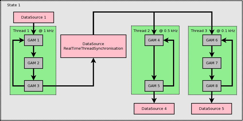
The threads synchronising can run at a frequency which is sub-multiple of the master (i.e. the one with the GAM writing to the DataSource) thread frequency . This is expressed by asking for a number of samples (> 1) to the RealTimeThreadSynchronisation DataSource.
The RealTimeThreadAsyncBridge component also allows to exchange data between threads without an explicit synchronisation point. This means that the consumer threads will use the latest available data.
Examples
GAMGroup and Ranges
In the RealTimeApplication example below, note that only the name of the parent GAMGroup has to be set for scheduling (as opposed to individually listing all of its internal GAM members).
Note also how the Ranges can be used to only access a subset of an array.
  1$TestApp = {
  2    Class = RealTimeApplication
  3    +Functions = {
  4        Class = ReferenceContainer
  5        +GAMTimer = {
  6            Class = IOGAM
  7            InputSignals = {
  8                Counter = {
  9                    DataSource = Timer
 10                    Type = uint32
 11                }
 12                Time = {
 13                    Frequency = 1
 14                    DataSource = Timer
 15                    Type = uint32
 16                }
 17            }
 18            OutputSignals = {
 19                Counter = {
 20                    DataSource = DDB1
 21                    Type = uint32
 22                }
 23                Time = {
 24                    DataSource = DDB1
 25                    Type = uint32
 26                }
 27            }
 28        }
 29        +GAMFixed1 = {
 30            Class = FixedGAMExample1
 31            Gain = 2
 32            InputSignals = {
 33                Counter = {
 34                    DataSource = DDB1
 35                    Type = uint32
 36                }
 37            }
 38            OutputSignals = {
 39                GainCounter = {
 40                    DataSource = DDB1
 41                    Type = uint32
 42                }
 43            }
 44        }
 45        +GAMGroup1 = {
 46            Class = ParentGAMGroupExample1
 47            Model = {{2, 0, 0}, {0, 3, 0}, {1, 0, 4}}
 48            +GAMChild1 = {
 49                Class = ChildGAMGroupExample1
 50                InputSignals = {
 51                    Signal3 = {
 52                        DataSource = DDB1
 53                        Type = uint32
 54                        NumberOfDimensions = 1
 55                        NumberOfElements = 3
 56                    }
 57                }
 58                OutputSignals = {
 59                    Signal1 = {
 60                        DataSource = DDB1
 61                        Type = uint32
 62                        NumberOfDimensions = 1
 63                        NumberOfElements = 3
 64                        Default = {1, 1, 1}
 65                    }
 66                 }
 67            }
 68            +GAMChild2 = {
 69                Class = ChildGAMGroupExample2
 70                InputSignals = {
 71                    Signal1 = {
 72                        DataSource = DDB1
 73                        Type = uint32
 74                        NumberOfDimensions = 1
 75                        NumberOfElements = 3
 76                    }
 77                }
 78                OutputSignals = {
 79                    Signal2 = {
 80                        DataSource = DDB1
 81                        Type = uint32
 82                        NumberOfDimensions = 1
 83                        NumberOfElements = 3
 84                        Default = {1, 1, 1}
 85                    }
 86                 }
 87            }
 88            +GAMChild3 = {
 89                Class = ChildGAMGroupExample1
 90                InputSignals = {
 91                    Signal2 = {
 92                        DataSource = DDB1
 93                        Type = uint32
 94                        NumberOfDimensions = 1
 95                        NumberOfElements = 3
 96                    }
 97                }
 98                OutputSignals = {
 99                    Signal3 = {
100                        DataSource = DDB1
101                        Type = uint32
102                        NumberOfDimensions = 1
103                        NumberOfElements = 3
104                        Default = {1, 1, 1}
105                    }
106                }
107             }
108        }
109        +GAMDisplay = {
110            Class = IOGAM
111            InputSignals = {
112                Counter = {
113                    DataSource = DDB1
114                    Type = uint32
115                }
116                GainCounter = {
117                    DataSource = DDB1
118                    Type = uint32
119                }
120                Signal1 = {
121                    DataSource = DDB1
122                    Type = uint32
123                }
124                Signal2 = {
125                    DataSource = DDB1
126                    Type = uint32
127                }
128                //Print only the first and the last element of Signal 3
129                Signal3 = {
130                    DataSource = DDB1
131                    Type = uint32
132                    Ranges = {{0,0}, {2, 2}}
133                    NumberOfElements = 3
134                    NumberOfDimensions = 1
135                }
136            }
137            OutputSignals = {
138                Counter = {
139                    DataSource = LoggerDataSource
140                    Type = uint32
141                }
142                GainCounter = {
143                    DataSource = LoggerDataSource
144                    Type = uint32
145                }
146                Signal1 = {
147                    DataSource = LoggerDataSource
148                    Type = uint32
149                    NumberOfElements = 3
150                    NumberOfDimensions = 1
151                }
152                Signal2 = {
153                    DataSource = LoggerDataSource
154                    Type = uint32
155                    NumberOfElements = 3
156                    NumberOfDimensions = 1
157                }
158                Signal3FirstAndLast = {
159                    DataSource = LoggerDataSource
160                    Type = uint32
161                    NumberOfElements = 2
162                    NumberOfDimensions = 1
163                }
164            }
165        }
166    }
167    +Data = {
168        Class = ReferenceContainer
169        DefaultDataSource = DDB1
170        +DDB1 = {
171            Class = GAMDataSource
172        }
173        +LoggerDataSource = {
174            Class = LoggerDataSource
175        }
176        +Timings = {
177            Class = TimingDataSource
178        }
179        +Timer = {
180            Class = LinuxTimer
181            SleepNature = "Default"
182            Signals = {
183                Counter = {
184                    Type = uint32
185                }
186                Time = {
187                    Type = uint32
188                }
189            }
190        }
191    }
192    +States = {
193        Class = ReferenceContainer
194        +State1 = {
195            Class = RealTimeState
196            +Threads = {
197                Class = ReferenceContainer
198                +Thread1 = {
199                    Class = RealTimeThread
200                    CPUs = 0x1
201                    //Note that only the GAMGroup1 has to be scheduled for execution (all the GAMGroup child GAMs will be automatically executed)
202                    Functions = {GAMTimer GAMFixed1 GAMGroup1 GAMDisplay }
203                }
204            }
205        }
206    }
207    +Scheduler = {
208        Class = GAMScheduler
209        TimingDataSource = Timings
210    }
211}
Execution times
The following is an example of a RealTimeApplication which prints the execution times of the real-time thread and of the GAMs (including the brokers’ read/write times).
  1$TestApp = {
  2    Class = RealTimeApplication
  3    +Functions = {
  4        Class = ReferenceContainer
  5        +GAMTimer = {
  6            Class = IOGAM
  7            InputSignals = {
  8                Counter = {
  9                    DataSource = Timer
 10                    Type = uint32
 11                }
 12                Time = {
 13                    Frequency = 1
 14                    DataSource = Timer
 15                    Type = uint32
 16                }
 17            }
 18            OutputSignals = {
 19                Counter = {
 20                    DataSource = DDB1
 21                    Type = uint32
 22                }
 23                Time = {
 24                    DataSource = DDB1
 25                    Type = uint32
 26                }
 27            }
 28        }
 29        +GAMFixed1 = {
 30            Class = FixedGAMExample1
 31            Gain = 2
 32            InputSignals = {
 33                Counter = {
 34                    DataSource = DDB1
 35                    Type = uint32
 36                }
 37            }
 38            OutputSignals = {
 39                GainCounter = {
 40                    DataSource = DDB1
 41                    Type = uint32
 42                }
 43            }
 44        }
 45        +GAMDisplay = {
 46            Class = IOGAM
 47            InputSignals = {
 48                Counter = {
 49                    DataSource = DDB1
 50                    Type = uint32
 51                }
 52                GainCounter = {
 53                    DataSource = DDB1
 54                    Type = uint32
 55                }
 56                State1_Thread1_CycleTime = {
 57                    Alias = State1.Thread1_CycleTime
 58                    DataSource = Timings
 59                    Type = uint32
 60                }
 61                GAMTimer_ReadTime = {
 62                    DataSource = Timings
 63                    Type = uint32
 64                }
 65                GAMTimer_ExecTime = {
 66                    DataSource = Timings
 67                    Type = uint32
 68                }
 69                GAMTimer_WriteTime = {
 70                    DataSource = Timings
 71                    Type = uint32
 72                }
 73                GAMFixed1_ReadTime = {
 74                    DataSource = Timings
 75                    Type = uint32
 76                }
 77                GAMFixed1_ExecTime = {
 78                    DataSource = Timings
 79                    Type = uint32
 80                }
 81                GAMFixed1_WriteTime = {
 82                    DataSource = Timings
 83                    Type = uint32
 84                }
 85            }
 86            OutputSignals = {
 87                Counter = {
 88                    DataSource = LoggerDataSource
 89                    Type = uint32
 90                }
 91                GainCounter = {
 92                    DataSource = LoggerDataSource
 93                    Type = uint32
 94                }
 95                State1_Thread1_CycleTime = {
 96                    DataSource = LoggerDataSource
 97                    Type = uint32
 98                }
 99                GAMTimer_ReadTime = {
100                    DataSource = LoggerDataSource
101                    Type = uint32
102                }
103                GAMTimer_ExecTime = {
104                    DataSource = LoggerDataSource
105                    Type = uint32
106                }
107                GAMTimer_WriteTime = {
108                    DataSource = LoggerDataSource
109                    Type = uint32
110                }
111                GAMFixed1_ReadTime = {
112                    DataSource = LoggerDataSource
113                    Type = uint32
114                }
115                GAMFixed1_ExecTime = {
116                    DataSource = LoggerDataSource
117                    Type = uint32
118                }
119                GAMFixed1_WriteTime = {
120                    DataSource = LoggerDataSource
121                    Type = uint32
122                }
123            }
124        }
125    }
126    +Data = {
127        Class = ReferenceContainer
128        DefaultDataSource = DDB1
129        +DDB1 = {
130            Class = GAMDataSource
131       	}
132        +LoggerDataSource = {
133            Class = LoggerDataSource
134        }
135        +Timings = {
136            Class = TimingDataSource
137        }
138        +Timer = {
139            Class = LinuxTimer
140            SleepNature = "Default"
141            Signals = {
142                Counter = {
143                    Type = uint32
144                }
145                Time = {
146                    Type = uint32
147                }
148            }
149        }
150    }
151    +States = {
152        Class = ReferenceContainer
153        +State1 = {
154            Class = RealTimeState
155            +Threads = {
156                Class = ReferenceContainer
157                +Thread1 = {
158                    Class = RealTimeThread
159                    CPUs = 0x1
160                    Functions = {GAMTimer GAMFixed1 GAMDisplay }
161                }
162            }
163        }
164    }
165    +Scheduler = {
166        Class = GAMScheduler
167        TimingDataSource = Timings
168    }
169}
Multiple states
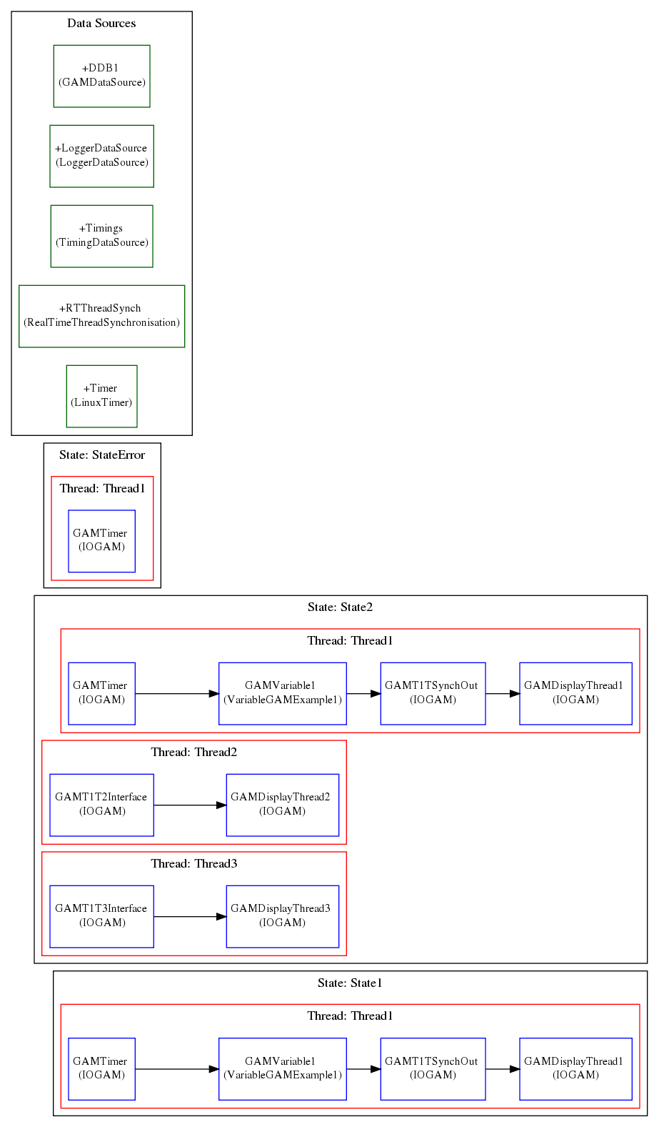
This is an example of a RealTimeApplication with two states. The custom component TCPSocketMessageProxyExample forwards TCP messages into MARTe messages.
Start the application with the -m parameter.
In order to change state, start the application and, in another console, type echo -e "Destination=StateMachine\nFunction=GOTOSTATE2" | nc 127.0.0.1 24680.
1+TCPMessageProxy = {
2 Class = TCPSocketMessageProxyExample
3 Port = 24680
4}
5+StateMachine = {
6 Class = StateMachine
7 +INITIAL = {
8 Class = ReferenceContainer
9 +START = {
10 Class = StateMachineEvent
11 NextState = "STATE1"
12 NextStateError = "ERROR"
13 Timeout = 0
14 +ChangeToState1Msg = {
15 Class = Message
16 Destination = TestApp
17 Mode = ExpectsReply
18 Function = PrepareNextState
19 +Parameters = {
20 Class = ConfigurationDatabase
21 param1 = State1
22 }
23 }
24 +StartNextStateExecutionMsg = {
25 Class = Message
26 Destination = TestApp
27 Function = StartNextStateExecution
28 Mode = ExpectsReply
29 }
30 }
31 }
32 +STATE1 = {
33 Class = ReferenceContainer
34 +GOTOSTATE2 = {
35 Class = StateMachineEvent
36 NextState = "STATE2"
37 NextStateError = "ERROR"
38 Timeout = 0
39 +PrepareChangeToState2Msg = {
40 Class = Message
41 Destination = TestApp
42 Mode = ExpectsReply
43 Function = PrepareNextState
44 +Parameters = {
45 Class = ConfigurationDatabase
46 param1 = State2
47 }
48 }
49 +StopCurrentStateExecutionMsg = {
50 Class = Message
51 Destination = TestApp
52 Function = StopCurrentStateExecution
53 Mode = ExpectsReply
54 }
55 +StartNextStateExecutionMsg = {
56 Class = Message
57 Destination = TestApp
58 Function = StartNextStateExecution
59 Mode = ExpectsReply
60 }
61 }
62 +ERROR = {
63 Class = StateMachineEvent
64 NextState = "ERROR"
65 NextStateError = "ERROR"
66 }
67 }
68 +STATE2 = {
69 Class = ReferenceContainer
70 +GOTOSTATE1 = {
71 Class = StateMachineEvent
72 NextState = "STATE1"
73 NextStateError = "ERROR"
74 Timeout = 0
75 +PrepareChangeToState1Msg = {
76 Class = Message
77 Destination = TestApp
78 Mode = ExpectsReply
79 Function = PrepareNextState
80 +Parameters = {
81 Class = ConfigurationDatabase
82 param1 = State1
83 }
84 }
85 +StopCurrentStateExecutionMsg = {
86 Class = Message
87 Destination = TestApp
88 Function = StopCurrentStateExecution
89 Mode = ExpectsReply
90 }
91 +StartNextStateExecutionMsg = {
92 Class = Message
93 Destination = TestApp
94 Function = StartNextStateExecution
95 Mode = ExpectsReply
96 }
97 }
98 +ERROR = {
99 Class = StateMachineEvent
100 NextState = "ERROR"
101 NextStateError = "ERROR"
102 }
103 }
104 +ERROR = {
105 Class = ReferenceContainer
106 +ENTER = {
107 Class = ReferenceContainer
108 +StopCurrentStateExecutionMsg = {
109 Class = Message
110 Destination = TestApp
111 Function = StopCurrentStateExecution
112 Mode = ExpectsReply
113 }
114 +PrepareChangeToErrorMsg = {
115 Class = Message
116 Destination = TestApp
117 Mode = ExpectsReply
118 Function = PrepareNextState
119 +Parameters = {
120 Class = ConfigurationDatabase
121 param1 = StateError
122 }
123 }
124 +StartNextStateExecutionMsg = {
125 Class = Message
126 Destination = TestApp
127 Function = StartNextStateExecution
128 Mode = ExpectsReply
129 }
130 }
131 +RESET = {
132 Class = StateMachineEvent
133 NextState = "STATE1"
134 NextStateError = "STATE1"
135 Timeout = 0
136 +StopCurrentStateExecutionMsg = {
137 Class = Message
138 Destination = TestApp
139 Function = StopCurrentStateExecution
140 Mode = ExpectsReply
141 }
142 +PrepareChangeToState1Msg = {
143 Class = Message
144 Destination = TestApp
145 Mode = ExpectsReply
146 Function = PrepareNextState
147 +Parameters = {
148 Class = ConfigurationDatabase
149 param1 = State1
150 }
151 }
152 +StartNextStateExecutionMsg = {
153 Class = Message
154 Destination = TestApp
155 Function = StartNextStateExecution
156 Mode = ExpectsReply
157 }
158 }
159 }
160}
161$TestApp = {
162 Class = RealTimeApplication
163 +Functions = {
164 Class = ReferenceContainer
165 +GAMTimer = {
166 Class = IOGAM
167 InputSignals = {
168 Counter = {
169 DataSource = Timer
170 Type = uint32
171 }
172 Time = {
173 Frequency = 1
174 DataSource = Timer
175 Type = uint32
176 }
177 }
178 OutputSignals = {
179 Counter = {
180 DataSource = DDB1
181 Type = uint32
182 }
183 Time = {
184 DataSource = DDB1
185 Type = uint32
186 }
187 }
188 }
189 +GAMVariable1 = {
190 Class = VariableGAMExample1
191 Gains = {2, 3, 4}
192 InputSignals = {
193 Counter = {
194 DataSource = DDB1
195 Type = uint32
196 }
197 }
198 OutputSignals = {
199 GainCounter1Thread1 = {
200 DataSource = DDB1
201 Type = uint32
202 }
203 GainCounter2Thread1 = {
204 DataSource = DDB1
205 Type = uint32
206 }
207 GainCounter3Thread1 = {
208 DataSource = DDB1
209 Type = uint32
210 }
211 }
212 }
213 +GAMT1TSynchOut = {
214 Class = IOGAM
215 InputSignals = {
216 GainCounter1Thread1 = {
217 DataSource = DDB1
218 Type = uint32
219 }
220 GainCounter2Thread1 = {
221 DataSource = DDB1
222 Type = uint32
223 }
224 GainCounter3Thread1 = {
225 DataSource = DDB1
226 Type = uint32
227 }
228 }
229 OutputSignals = {
230 GainCounter1Thread1 = {
231 DataSource = RTThreadSynch
232 Type = uint32
233 }
234 GainCounter2Thread1 = {
235 DataSource = RTThreadSynch
236 Type = uint32
237 }
238 GainCounter3Thread1 = {
239 DataSource = RTThreadSynch
240 Type = uint32
241 }
242 }
243 }
244 +GAMT1T2Interface = {
245 Class = IOGAM
246 InputSignals = {
247 GainCounter1Thread1 = {
248 DataSource = RTThreadSynch
249 Type = uint32
250 Samples = 2 //Run at half the frequency of thread 1
251 }
252 GainCounter2Thread1 = {
253 DataSource = RTThreadSynch
254 Type = uint32
255 Samples = 2 //Run at half the frequency of thread 1
256 }
257 GainCounter3Thread1 = {
258 DataSource = RTThreadSynch
259 Type = uint32
260 Samples = 2 //Run at half the frequency of thread 1
261 }
262 }
263 OutputSignals = {
264 GainCounter1Thread2 = {
265 DataSource = DDB1
266 Type = uint32
267 Samples = 1
268 NumberOfDimensions = 1
269 NumberOfElements = 2 //2 elements for each cycle (as it waits for 2 samples)
270 }
271 GainCounter2Thread2 = {
272 DataSource = DDB1
273 Type = uint32
274 Samples = 1
275 NumberOfDimensions = 1
276 NumberOfElements = 2 //2 elements for each cycle (as it waits for 2 samples)
277 }
278 GainCounter3Thread2 = {
279 DataSource = DDB1
280 Type = uint32
281 Samples = 1
282 NumberOfDimensions = 1
283 NumberOfElements = 2 //2 elements for each cycle (as it waits for 2 samples)
284 }
285 }
286 }
287 +GAMT1T3Interface = {
288 Class = IOGAM
289 InputSignals = {
290 GainCounter1Thread1 = {
291 DataSource = RTThreadSynch
292 Type = uint32
293 Samples = 4 //Run at one quarter of the frequency of thread 1
294 }
295 GainCounter2Thread1 = {
296 DataSource = RTThreadSynch
297 Type = uint32
298 Samples = 4 //Run at one quarter the frequency of thread 1
299 }
300 GainCounter3Thread1 = {
301 DataSource = RTThreadSynch
302 Type = uint32
303 Samples = 4 //Run at one quarter the frequency of thread 1
304 }
305 }
306 OutputSignals = {
307 GainCounter1Thread3 = {
308 DataSource = DDB1
309 Type = uint32
310 Samples = 1
311 NumberOfDimensions = 1
312 NumberOfElements = 4 //4 elements for each cycle (as it waits for 4 samples)
313 }
314 GainCounter2Thread3 = {
315 DataSource = DDB1
316 Type = uint32
317 Samples = 1
318 NumberOfDimensions = 1
319 NumberOfElements = 4 //4 elements for each cycle (as it waits for 4 samples)
320 }
321 GainCounter3Thread3 = {
322 DataSource = DDB1
323 Type = uint32
324 Samples = 1
325 NumberOfDimensions = 1
326 NumberOfElements = 4 //4 elements for each cycle (as it waits for 4 samples)
327 }
328 }
329 }
330 +GAMDisplayThread1 = {
331 Class = IOGAM
332 InputSignals = {
333 Counter = {
334 DataSource = DDB1
335 Type = uint32
336 }
337 GainCounter1Thread1 = {
338 DataSource = DDB1
339 Type = uint32
340 }
341 GainCounter2Thread1 = {
342 DataSource = DDB1
343 Type = uint32
344 }
345 GainCounter3Thread1 = {
346 DataSource = DDB1
347 Type = uint32
348 }
349 }
350 OutputSignals = {
351 Counter = {
352 DataSource = LoggerDataSource
353 Type = uint32
354 }
355 GainCounter1Thread1 = {
356 DataSource = LoggerDataSource
357 Type = uint32
358 }
359 GainCounter2Thread1 = {
360 DataSource = LoggerDataSource
361 Type = uint32
362 }
363 GainCounter3Thread1 = {
364 DataSource = LoggerDataSource
365 Type = uint32
366 }
367 }
368 }
369 +GAMDisplayThread2 = {
370 Class = IOGAM
371 InputSignals = {
372 GainCounter1Thread2 = {
373 DataSource = DDB1
374 Type = uint32
375 }
376 GainCounter2Thread2 = {
377 DataSource = DDB1
378 Type = uint32
379 }
380 GainCounter3Thread2 = {
381 DataSource = DDB1
382 Type = uint32
383 }
384 }
385 OutputSignals = {
386 GainCounter1Thread2 = {
387 DataSource = LoggerDataSource
388 Type = uint32
389 NumberOfDimensions = 1
390 NumberOfElements = 2
391 }
392 GainCounter2Thread2 = {
393 DataSource = LoggerDataSource
394 Type = uint32
395 NumberOfDimensions = 1
396 NumberOfElements = 2
397 }
398 GainCounter3Thread2 = {
399 DataSource = LoggerDataSource
400 Type = uint32
401 NumberOfDimensions = 1
402 NumberOfElements = 2
403 }
404 }
405 }
406 +GAMDisplayThread3 = {
407 Class = IOGAM
408 InputSignals = {
409 GainCounter1Thread3 = {
410 DataSource = DDB1
411 Type = uint32
412 }
413 GainCounter2Thread3 = {
414 DataSource = DDB1
415 Type = uint32
416 }
417 GainCounter3Thread3 = {
418 DataSource = DDB1
419 Type = uint32
420 }
421 }
422 OutputSignals = {
423 GainCounter1Thread3 = {
424 DataSource = LoggerDataSource
425 Type = uint32
426 NumberOfDimensions = 1
427 NumberOfElements = 4
428 }
429 GainCounter2Thread3 = {
430 DataSource = LoggerDataSource
431 Type = uint32
432 NumberOfDimensions = 1
433 NumberOfElements = 4
434 }
435 GainCounter3Thread3 = {
436 DataSource = LoggerDataSource
437 Type = uint32
438 NumberOfDimensions = 1
439 NumberOfElements = 4
440 }
441 }
442 }
443 }
444 +Data = {
445 Class = ReferenceContainer
446 DefaultDataSource = DDB1
447 +DDB1 = {
448 Class = GAMDataSource
449 }
450 +LoggerDataSource = {
451 Class = LoggerDataSource
452 }
453 +Timings = {
454 Class = TimingDataSource
455 }
456 +RTThreadSynch = {
457 Class = RealTimeThreadSynchronisation
458 Timeout = 5000 //Timeout in ms to wait for the thread to cycle.
459 }
460 +Timer = {
461 Class = LinuxTimer
462 SleepNature = "Default"
463 Signals = {
464 Counter = {
465 Type = uint32
466 }
467 Time = {
468 Type = uint32
469 }
470 }
471 }
472 }
473 +States = {
474 Class = ReferenceContainer
475 +State1 = {
476 Class = RealTimeState
477 +Threads = {
478 Class = ReferenceContainer
479 +Thread1 = {
480 Class = RealTimeThread
481 CPUs = 0x1
482 Functions = {GAMTimer GAMVariable1 GAMT1TSynchOut GAMDisplayThread1}
483 }
484 }
485 }
486 +State2 = {
487 Class = RealTimeState
488 +Threads = {
489 Class = ReferenceContainer
490 +Thread1 = {
491 Class = RealTimeThread
492 CPUs = 0x1
493 Functions = {GAMTimer GAMVariable1 GAMT1TSynchOut GAMDisplayThread1}
494 }
495 +Thread2 = {
496 Class = RealTimeThread
497 CPUs = 0x2
498 Functions = {GAMT1T2Interface GAMDisplayThread2}
499 }
500 +Thread3 = {
501 Class = RealTimeThread
502 CPUs = 0x4
503 Functions = {GAMT1T3Interface GAMDisplayThread3}
504 }
505 }
506 }
507 +StateError = {
508 Class = RealTimeState
509 +Threads = {
510 Class = ReferenceContainer
511 +Thread1 = {
512 Class = RealTimeThread
513 CPUs = 0x1
514 Functions = {GAMTimer}
515 }
516 }
517 }
518 }
519 +Scheduler = {
520 Class = GAMScheduler
521 TimingDataSource = Timings
522 }
523}
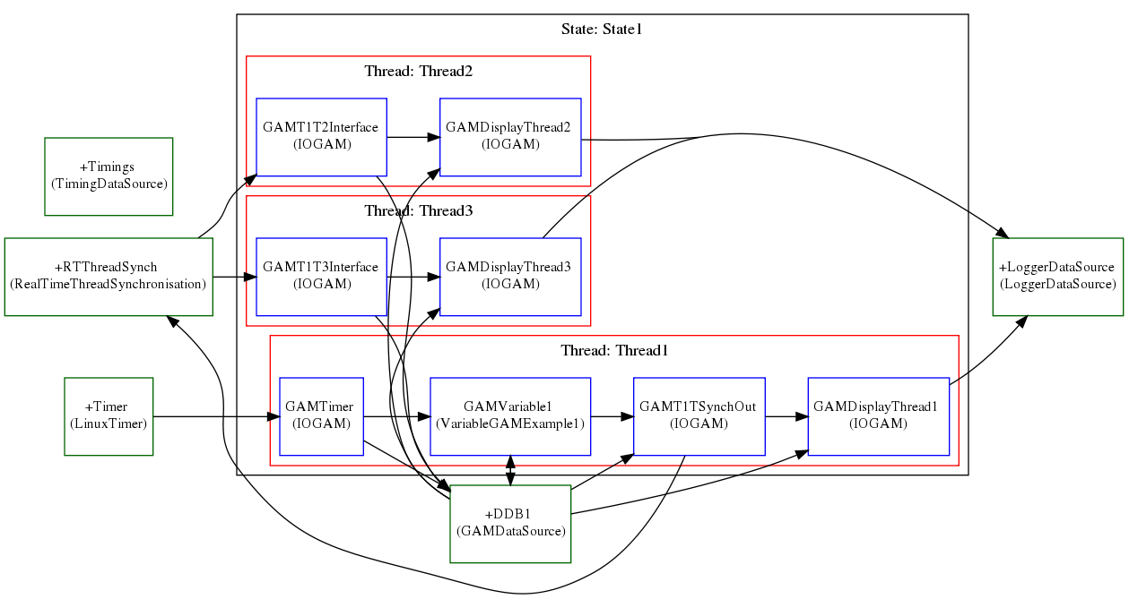
Thread Synchronisation
The following is an example of a RealTimeApplication with multiple synchronised threads. Note that the Thread2 and the Thread3 run at a sub-frequency of Thread1.
1$TestApp = {
2 Class = RealTimeApplication
3 +Functions = {
4 Class = ReferenceContainer
5 +GAMTimer = {
6 Class = IOGAM
7 InputSignals = {
8 Counter = {
9 DataSource = Timer
10 Type = uint32
11 }
12 Time = {
13 Frequency = 1
14 DataSource = Timer
15 Type = uint32
16 }
17 }
18 OutputSignals = {
19 Counter = {
20 DataSource = DDB1
21 Type = uint32
22 }
23 Time = {
24 DataSource = DDB1
25 Type = uint32
26 }
27 }
28 }
29 +GAMVariable1 = {
30 Class = VariableGAMExample1
31 Gains = {2, 3, 4}
32 InputSignals = {
33 Counter = {
34 DataSource = DDB1
35 Type = uint32
36 }
37 }
38 OutputSignals = {
39 GainCounter1Thread1 = {
40 DataSource = DDB1
41 Type = uint32
42 }
43 GainCounter2Thread1 = {
44 DataSource = DDB1
45 Type = uint32
46 }
47 GainCounter3Thread1 = {
48 DataSource = DDB1
49 Type = uint32
50 }
51 }
52 }
53 +GAMT1TSynchOut = {
54 Class = IOGAM
55 InputSignals = {
56 GainCounter1Thread1 = {
57 DataSource = DDB1
58 Type = uint32
59 }
60 GainCounter2Thread1 = {
61 DataSource = DDB1
62 Type = uint32
63 }
64 GainCounter3Thread1 = {
65 DataSource = DDB1
66 Type = uint32
67 }
68 }
69 OutputSignals = {
70 GainCounter1Thread1 = {
71 DataSource = RTThreadSynch
72 Type = uint32
73 }
74 GainCounter2Thread1 = {
75 DataSource = RTThreadSynch
76 Type = uint32
77 }
78 GainCounter3Thread1 = {
79 DataSource = RTThreadSynch
80 Type = uint32
81 }
82 }
83 }
84 +GAMT1T2Interface = {
85 Class = IOGAM
86 InputSignals = {
87 GainCounter1Thread1 = {
88 DataSource = RTThreadSynch
89 Type = uint32
90 Samples = 2 //Run at half the frequency of thread 1
91 }
92 GainCounter2Thread1 = {
93 DataSource = RTThreadSynch
94 Type = uint32
95 Samples = 2 //Run at half the frequency of thread 1
96 }
97 GainCounter3Thread1 = {
98 DataSource = RTThreadSynch
99 Type = uint32
100 Samples = 2 //Run at half the frequency of thread 1
101 }
102 }
103 OutputSignals = {
104 GainCounter1Thread2 = {
105 DataSource = DDB1
106 Type = uint32
107 Samples = 1
108 NumberOfDimensions = 1
109 NumberOfElements = 2 //2 elements for each cycle (as it waits for 2 samples)
110 }
111 GainCounter2Thread2 = {
112 DataSource = DDB1
113 Type = uint32
114 Samples = 1
115 NumberOfDimensions = 1
116 NumberOfElements = 2 //2 elements for each cycle (as it waits for 2 samples)
117 }
118 GainCounter3Thread2 = {
119 DataSource = DDB1
120 Type = uint32
121 Samples = 1
122 NumberOfDimensions = 1
123 NumberOfElements = 2 //2 elements for each cycle (as it waits for 2 samples)
124 }
125 }
126 }
127 +GAMT1T3Interface = {
128 Class = IOGAM
129 InputSignals = {
130 GainCounter1Thread1 = {
131 DataSource = RTThreadSynch
132 Type = uint32
133 Samples = 4 //Run at one quarter of the frequency of thread 1
134 }
135 GainCounter2Thread1 = {
136 DataSource = RTThreadSynch
137 Type = uint32
138 Samples = 4 //Run at one quarter the frequency of thread 1
139 }
140 GainCounter3Thread1 = {
141 DataSource = RTThreadSynch
142 Type = uint32
143 Samples = 4 //Run at one quarter the frequency of thread 1
144 }
145 }
146 OutputSignals = {
147 GainCounter1Thread3 = {
148 DataSource = DDB1
149 Type = uint32
150 Samples = 1
151 NumberOfDimensions = 1
152 NumberOfElements = 4 //4 elements for each cycle (as it waits for 4 samples)
153 }
154 GainCounter2Thread3 = {
155 DataSource = DDB1
156 Type = uint32
157 Samples = 1
158 NumberOfDimensions = 1
159 NumberOfElements = 4 //4 elements for each cycle (as it waits for 4 samples)
160 }
161 GainCounter3Thread3 = {
162 DataSource = DDB1
163 Type = uint32
164 Samples = 1
165 NumberOfDimensions = 1
166 NumberOfElements = 4 //4 elements for each cycle (as it waits for 4 samples)
167 }
168 }
169 }
170 +GAMDisplayThread1 = {
171 Class = IOGAM
172 InputSignals = {
173 Counter = {
174 DataSource = DDB1
175 Type = uint32
176 }
177 GainCounter1Thread1 = {
178 DataSource = DDB1
179 Type = uint32
180 }
181 GainCounter2Thread1 = {
182 DataSource = DDB1
183 Type = uint32
184 }
185 GainCounter3Thread1 = {
186 DataSource = DDB1
187 Type = uint32
188 }
189 }
190 OutputSignals = {
191 Counter = {
192 DataSource = LoggerDataSource
193 Type = uint32
194 }
195 GainCounter1Thread1 = {
196 DataSource = LoggerDataSource
197 Type = uint32
198 }
199 GainCounter2Thread1 = {
200 DataSource = LoggerDataSource
201 Type = uint32
202 }
203 GainCounter3Thread1 = {
204 DataSource = LoggerDataSource
205 Type = uint32
206 }
207 }
208 }
209 +GAMDisplayThread2 = {
210 Class = IOGAM
211 InputSignals = {
212 GainCounter1Thread2 = {
213 DataSource = DDB1
214 Type = uint32
215 }
216 GainCounter2Thread2 = {
217 DataSource = DDB1
218 Type = uint32
219 }
220 GainCounter3Thread2 = {
221 DataSource = DDB1
222 Type = uint32
223 }
224 }
225 OutputSignals = {
226 GainCounter1Thread2 = {
227 DataSource = LoggerDataSource
228 Type = uint32
229 NumberOfDimensions = 1
230 NumberOfElements = 2
231 }
232 GainCounter2Thread2 = {
233 DataSource = LoggerDataSource
234 Type = uint32
235 NumberOfDimensions = 1
236 NumberOfElements = 2
237 }
238 GainCounter3Thread2 = {
239 DataSource = LoggerDataSource
240 Type = uint32
241 NumberOfDimensions = 1
242 NumberOfElements = 2
243 }
244 }
245 }
246 +GAMDisplayThread3 = {
247 Class = IOGAM
248 InputSignals = {
249 GainCounter1Thread3 = {
250 DataSource = DDB1
251 Type = uint32
252 }
253 GainCounter2Thread3 = {
254 DataSource = DDB1
255 Type = uint32
256 }
257 GainCounter3Thread3 = {
258 DataSource = DDB1
259 Type = uint32
260 }
261 }
262 OutputSignals = {
263 GainCounter1Thread3 = {
264 DataSource = LoggerDataSource
265 Type = uint32
266 NumberOfDimensions = 1
267 NumberOfElements = 4
268 }
269 GainCounter2Thread3 = {
270 DataSource = LoggerDataSource
271 Type = uint32
272 NumberOfDimensions = 1
273 NumberOfElements = 4
274 }
275 GainCounter3Thread3 = {
276 DataSource = LoggerDataSource
277 Type = uint32
278 NumberOfDimensions = 1
279 NumberOfElements = 4
280 }
281 }
282 }
283 }
284 +Data = {
285 Class = ReferenceContainer
286 DefaultDataSource = DDB1
287 +DDB1 = {
288 Class = GAMDataSource
289 }
290 +LoggerDataSource = {
291 Class = LoggerDataSource
292 }
293 +Timings = {
294 Class = TimingDataSource
295 }
296 +RTThreadSynch = {
297 Class = RealTimeThreadSynchronisation
298 Timeout = 10000 //Timeout in ms to wait for the thread to cycle.
299 }
300 +Timer = {
301 Class = LinuxTimer
302 SleepNature = "Default"
303 Signals = {
304 Counter = {
305 Type = uint32
306 }
307 Time = {
308 Type = uint32
309 }
310 }
311 }
312 }
313 +States = {
314 Class = ReferenceContainer
315 +State1 = {
316 Class = RealTimeState
317 +Threads = {
318 Class = ReferenceContainer
319 +Thread1 = {
320 Class = RealTimeThread
321 CPUs = 0x1
322 Functions = {GAMTimer GAMVariable1 GAMT1TSynchOut GAMDisplayThread1 }
323 }
324 +Thread2 = {
325 Class = RealTimeThread
326 CPUs = 0x2
327 Functions = {GAMT1T2Interface GAMDisplayThread2 }
328 }
329 +Thread3 = {
330 Class = RealTimeThread
331 CPUs = 0x4
332 Functions = {GAMT1T3Interface GAMDisplayThread3 }
333 }
334 }
335 }
336 }
337 +Scheduler = {
338 Class = GAMScheduler
339 TimingDataSource = Timings
340 }
341}
Instructions on how to compile and execute the examples can be found here.