HotRIO Protocol
Introduction
The HotRIO communication protocol defines the physical interface, frame format, node topology, data-routing behavior, clock-tolerance compensation, timing distribution, and network-recovery mechanisms used by HotRIO modules.
The HotRIO communication protocol can operate in two modes.
In synchronous mode every node is driven by the clock recovered from data received from the previous node.
In CTC mode every node is driven by a local clock source, and communication is synchronized through a Clock Tolerance Compensation mechanism.
The CTC-based implementation decouples clock domains and maintains a stable data stream by inserting or removing designated skip sequences when required.
Scope
This document defines the FPGA firmware requirements for the HotRIO data-link protocol. The protocol connects one HotRIO master to one or more HotRIO slave modules. It supports single-ring and dual-ring configurations.
Payload generation, application-level interpretation of payload data, and the method used to assign a unique address to each slave are outside the scope of this document.
Hardware Overview and Physical Layer
The HotRIO protocol is not dependent on vendor-specific hardware, software, or firmware technology. It is intended for use on the following hardware platforms:
HotRIO modules with a Xilinx Zynq UltraScale+ FPGA (
XCZU9EG-1FFVC900E).HotRIO modules with a Lattice ECP5 FPGA.
HotRIO modules with a Lattice ECP5 FPGA that plug into a National Instruments CompactRIO chassis.
These platforms use SFP+ transceivers for the HotRIO physical interface. The supported media include:
Cables: SM fiber, MM fibers and SFP+ DAC Twinax cables
Full duplex: SFP+ fiber pair
Half duplex: Just one fiber used
The protocol can operate over a full-duplex fiber pair or, where supported by the hardware configuration, over a single fiber.
The serial line rate is 1.25 Gb/s. With 8b/10b encoding, the effective data
rate is 1 Gb/s and the parallel byte interface transfers one 8-bit value at
125 MHz.
Frame Format
HotRIO data is transmitted continuously. The nominal frame length is
50 bytes. A nominal frame contains a 2-byte prefix followed by four
12-byte packets:
Byte offset |
Size |
Content |
|---|---|---|
|
|
Frame marker, timing flag or skip character. |
|
|
Protocol identifier or epoch-time segment, depending on the marker. |
|
|
Four 12-byte packets. |

Figure 1. HotRIO 50-byte frame structure
Frame Markers
Frame markers are valid 8b/10b control characters that are distinct from ordinary 8-bit payload values. They identify frame boundaries and distribute timing information.
Character |
Name |
Purpose |
|---|---|---|
|
Start of Frame (SOF) |
Marks the beginning of a frame followed by one byte of epoch-time information in the following byte position. |
|
|
Marks a 4-microsecond timing boundary. |
|
|
Marks a 1-millisecond timing boundary. |
|
|
Marks a 1-second timing boundary. |
|
Skip character |
Supports clock-tolerance compensation. Under nominal timing, it occurs
|
The byte following a timing flag or skip character is the protocol identifier:
0xAAidentifies the HotRIO protocol.
The sequence K28.4 + 0xAA, constituted of a skip character followed by the
HotRIO protocol identifier, is called a “skip sequence”.
Epoch-Time Distribution
The HotRIO master distributes a 64-bit epoch-time value through eight SOF
frames. The value is divided into eight 8-bit segments. One segment is
transmitted in the byte immediately following each K28.5 SOF character.
Each slave reconstructs the complete 64-bit epoch-time value from the received
sequence.
The segment order must match the byte-order convention implemented by the master and slave firmware.
Master Timing-Marker Cadence
The master transmits a repeating 10-frame cadence. Each frame retains the nominal 50-byte structure: a 2-byte prefix followed by four 12-byte packets.
Frame position |
Prefix |
Purpose |
|---|---|---|
|
Timing marker + |
Marks the current timing boundary. The marker is selected from the
|
|
|
Transmits the first four bytes of the 64-bit epoch-time value. |
|
|
Transmits the skip character followed by the HotRIO protocol
identifier at the nominal |
|
|
Transmits the remaining four bytes of the 64-bit epoch-time value. |
After frame position 9, the next 10-frame cadence begins with the
appropriate timing marker and 0xAA protocol identifier. The downstream
slaves receive these nominal frames and may insert or remove eligible
K28.4 + 0xAA sequences when required by their CTC buffer occupancy.

Figure 2. 10-frame special character pattern. Note that 4U may be replaced by a milliscond or second marker.
Packet Format
Each HotRIO frame transports four packets. Each packet is 12 bytes long:
Field |
Size |
Description |
|---|---|---|
Address |
|
Identifies the destination node. |
Payload |
|
Carries application data. |
Control |
|
Carries parity and sideband information. |
Addresses conventions
Each slave node will have a unique address identifier. How this address is configured/assigned to each slave node is out of the scope of this document. The address of the packet defines to which node the data payload is destined for.
When a slave node receives a packet with its own address, the node will transmit a new packet whose address will be its own plus an offset.
The addresses of the packets included in a single HotRIO frame can be different.
Control Byte
Each Control Byte will have:
One parity bit for the odd bits of the address and packet payload (Po)
One parity bit for the even bits of the address and packet payload (Pe)
2 reserved bits for future applications
4 bits for side band communication for information to be exchanged between master micro controller and slave micro controllers of the HotRIO network .
The structure of the sideband bits in the control bytes is shown in Figure 3.

Figure 3. Structure of sideband information in the frame
The sideband bits of the first Control Byte in each frame are called “arbitration bits”. They contain information referring to the N-th slave node in a time-multiplexed scheme. Their function is detailed below:
Arbitration bit name |
Bit position in the Sideband Subframe |
Description |
|---|---|---|
|
|
Sel(n) is the flag set/reset by the Master HotRIO node to select each slave node for communication on the sideband. n Indicates the nth Sideband address, where the address is represented by the location of the transmitted HotRIO frame with respect to the millisecond flag. Example : if the sel(n) flag is set in the 4th frame after the milliseceond flag by the HotRIO master, the 4th HotRIO slave decodes the sideband subframe and recognizes that it is being addressed in the time multiplexed addressing scheme. All other slaves will bypass the sideband information without modifying it. |
|
|
This bit is used to indicate the mode of operation on the sideband Channel. In the normal mode of operation where the Master HotRIO node is aware of the Number of HotRIO slaves available, the Mode bit is set as 1 by the master for all the slaves, Indicating to the slaves that it is in Data Communicaiton Mode. If the Master HotRIO node sets the Mode bit as 0, all the slaves would switch to auto addressing mode, where each slave node would assign consecutive address to itself and indicate to the Master about the number of Slaves in the HotRIO network. |
|
|
This bit is used by the nth HotRIO slave to indicate to the HotRIO Master that it is ready to receive data from the master. This bit is set by the respective HotRIO Slave on its slot of addressing in the Time multiplexed Addressing scheme. |
|
|
This bit is used by the nth HotRIO slave to indicate to the HotRIO Master that it has data to be communicated to the HotRIO Master. This bit is set by the respective HotRIO Slave on its slot of addressing in the Time multiplexed Addressing scheme. |
The sideband bits of the second Control Byte in the frame are called “transfer information bits”. They contain information referring to the currently active sideband transaction. Their function is detailed below:
Transfer information Bit Name |
Bit position in the Sideband Subframe |
Description |
|---|---|---|
|
|
Rdy bit is used by the Master and the slave node to indicate to each other about the status of its readiness to accept data, during an active Data communication exchange between the Master and Selected HotRIO Slave. This bit can is by the two nodes on a real time basis. |
|
|
This bit is used to indicate the validity of the payload present in the data section of the HotRIO sideband Subframe. Both the Master and the selected slave can use this bit to set when valid data is being exchanged on a realtime basis. |
|
|
This bit is used to indicate the parity of the valid data being sent by the Master or slave node. It is a dont care bit when the data is not valid |
|
|
This bit is used to request a retransmission of the previous data transmitted incase there was an error in the received data. This bit can be set by either the master node or the selected Slave node on a realtime basis. |
The final two nibbles carry one byte of application data.
   Packet2                 Packet3

+-----------+          +-----------+
| Data[7:4] |          | Data[3:0] |
+-----------+          +-----------+

             │
             ▼

        Complete Data Byte
The upper nibble shall always be transmitted before the lower nibble.
Clocking Modes
HotRIO supports two different clocking modes: synchronous mode and CTC mode.
In synchronous mode every node is driven by the clock recovered from data received from the previous node. Thus, every node is synchronized with the Master HotRIO. This mode does not impose an intrinsic ppm requirement on the master clock frequency. In CTC mode every node is driven by a local clock source, and communication is synchronized through a Clock Tolerance Compensation mechanism. When using this mode, the “K28.4 AA” sequence may be skipped or duplicated to realign the TX data stream with the RX. This mechanism requires the local clocks to differ from 125 MHz by no more than 4000 ppm. It is suggested to apply some margin to this ppm limit, as it is the theoretical maximum.
Regardless of the clocking mode, there may be a stricter ppm requirement based on specific transceiver implementations.
Clock Tolerance Compensation
CTC Architecture
The CTC function is instantiated in each HotRIO slave module and in the HotRIO
master receive path. Each instance receives a HotRIO stream, buffers the
incoming data, and maintains a nominal frame length of 50 bytes by
inserting or removing K28.4 + 0xAA sequences at permitted boundaries.
In a slave, the CTC module forwards normalized frames through the local transmit clock domain to the next node. The final slave transmits the return stream back to the master. In the master receive path, the CTC module performs the same frame recognition and normalization before the returned data is processed locally.
This mechanism absorbs small differences between receive and transmit clock frequencies without modifying packet payload data.
The local clock frequency must remain within the tolerance supported by the buffer depth and correction interval.
Frame Types
The CTC module handles three frame lengths:
Frame type |
Length |
Description |
|---|---|---|
Normal frame |
|
Contains one valid 2-byte prefix. The frame may begin with an SOF and
epoch-time segment, a timing flag and protocol identifier, or
|
Long frame |
|
Contains two |
Short frame |
|
Does not begin with an SOF, timing flag, or skip character. The frame
starts directly with the packet address. The CTC module can insert
|
For a normal frame, the skip character behaves as the framing element for that specific frame. It provides a legal correction point without changing the four packet payloads.
Buffer-Occupancy Correction
The CTC module monitors buffer occupancy and applies skip-sequence correction when required:
At the almost-full threshold, the CTC module may remove an eligible
K28.4 + 0xAAsequence to drain the buffer.At the almost-empty threshold, the CTC module may insert
K28.4 + 0xAAto avoid buffer underflow.When occupancy is within the normal operating range, the CTC module normalizes a received 52-byte frame by removing one skip sequence and normalizes a received 48-byte frame by inserting one skip sequence.
Corrections will be applied only at valid skip-sequence boundaries. Packet address, payload, and control fields will not be modified by the CTC operation.
Master and Slave HotRIO
The HotRIO communication protocol will have two communication modes:
Master
Slave
The Master HotRIO should generate the clock for the data transmission, while the Slave HotRIO may either recover the clock from the incoming data or from a local source depending on the clocking mode.
The Master HotRIO should also generate the marker (sync, skip, 4us, 1ms, 1s) while the Slave HotRIO should transmit the marker that it has received.
Figures 4 amd 5 show a representation of the connection between the Master and Slave modules with a daisy chain connection, depending on the clocking mode.

Figure 4. Master and Slave HotRIO modules daisy chain connection (synchronous mode)
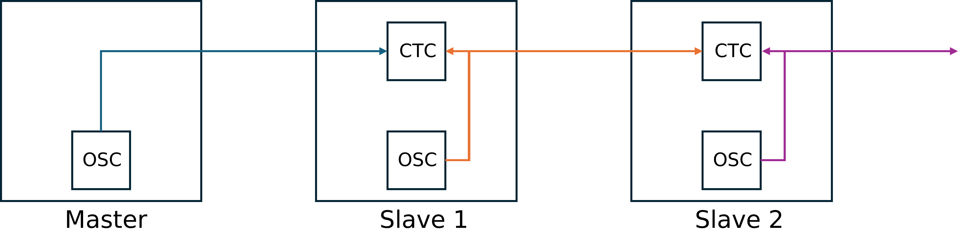
Figure 5. Master and Slave HotRIO modules daisy chain connection (CTC mode)
Master HotRIO
The Master HotRIO transmitter needs to:
Provide transmission data stream to specific addresses (nodes). The generation of this data stream is out of the scope of this document.
Trigger specific data production in the slave nodes by transmitting the corresponding address node.
The Master HotRIO receiver needs to:
Collect data from a set of addresses (nodes) (out of scope of this document).
Handle potentially different clock domains (transmitting and receiving).
A possible FW implementation for the Master HotRIO Transmitter is provided as reference in next points. Other equivalent or better approaches might be proposed:
Marker Generation
The Master HotRIO will generate its own clock (125MHz) and the markers for the “Start of Frame” (SoF) and synchronization (skip, 4us, ms and s).
A process with a counter could be implemented in the FPGA to identify when the different time or synchronization marks should be sent. Also, external PPS input can/will be used to reset the timing flags counters (1s, 1ms, 4us).
Control generation: parity bits
There should be a process or equivalent to calculate the two parity bits of the address + payload of each packet of the frame.
Master TX State Machine
The main goal of this state machine is to sequentially send the 50 bytes composing the HotRIO frame to the PCS/SERDES of the FPGA.
Possible names for this state machine could be:
FRAME: to send the required marker
ADDRESS: to send the address of the node. During this state, the payload should be sampled
DATA: to send the payload, one byte at a time
CONTROL: to send the control byte with updated parity bits.
To produce a HotRIO Frame, the flow should be:
FRAME -> 4 x [ADDRESS -> DATA (x10) -> CONTROL]
Master RX State Machine
A similar state machine could be built for the reception of frames in the master side:
FRAME: to identify the input marker
ADDRESS: to identify which node is providing data. During this state, the payload should be sampled.
DATA: to read the payload, byte by byte.
CONTROL: to check the SPI bits and to check parity bits to disregard/accept the received payload.
Note that the FRAME state should also accept receiving directly the address of the first packet when the nominal expected frame would start with a skip sequence.
The receiver clock will have the same frequency than the transmitter clock, although the phase might defer due to the different lenghts of fibers.
Slave HotRIO
Each Slave HotRIO module connected to the same daisy chain will have a unique address or identifier. The configuration of the nodes addresses is out of the scope of this document.
The Slave HotRIO will continuously forward the stream of data from the RX to the TX. For doing so, the Slave HotRIO RX should use the retrieved clock from the incoming data either directly in the Slave HotRIO TX or as an input to the CTC mechanism.
When the protocol ID of the incoming frame is not HotRIO, the next 48B will be forwarded from RX to TX. When the protocol ID is HotRIO, the state machine will check the address of each packet before forwarding data from RX to TX.
When the address of the incoming data does not match the address of the node, the Slave HotRIO TX will forward the received address + payload. The parity bits of the CONTROL byte are the only ones that are always re-calculated after reception and before re-transmission. If parity calculations in the Slave HotRIO do not match the received parity bits, both parity bits will be inverted in the forwarded CONTROL byte with respect to those calculated.
If the incoming address matches the node address, then the incoming payload is replaced by the data of the Slave HotRIO and an offset is added to the TX address.
A State Machine for the Slave HotRIO with similar states than the Master HotRIO could be implemented for the reception/transmission of the Slave HotRIO frames. The possible states could be:
FRAME: to receive/forward the input marker.
ADDRESS: if the incoming address is different from the node address, the system should forward the ADDRESS information to the TX. In case, the ADDRESS does match the node address, the offset will be added to the transmitted address.
DATA: Depending on the address value, in this state the system would forward/replace the incoming data. Payload should be transferred byte by byte.
CONTROL: In this state, the incoming parity bits should be checked and provide a “data_valid” signal. Also, the outgoing parity bits should be re-calculated based on incoming data. In case the TX is just forwarding the incoming data and one (or two) of the incoming parity bits is not correct, both transmitted parity bits of the CONTROL TX byte should be invalidated.
Single-Ring and Dual-Ring Operation
Single-Ring Operation
A single-ring configuration provides one continuous forwarding path through the HotRIO nodes. Each slave receives frames from the previous node, processes its addressed packets, and forwards the stream to the next node.
Dual-Ring Operation
A dual-ring configuration provides two HotRIO daisy-chain paths in opposite direction, called rings. It adds the following capabilities:
redundant data transport;
detection of node and network-path failures;
automatic network healing after a node or fiber failure;
timing-offset measurement between the master and the slave nodes; and
delay compensation for deterministic timing distribution.
DCU Channel Usage in Dual-Ring
The implementation uses DCU0 channel 0 and DCU1 channel 0 for the two
ring directions. These channels provide the receive-to-transmit forwarding
paths required for bidirectional operation.
Ring 1transfers data from DCU0 channel 0 RX to DCU1 channel 0 TXRing 2transfers data from DCU1 channel 0 RX to DCU0 channel 0 TX
Each node continuously monitors both receive paths. If one receive path is detected as broken, the node reroutes the healthy receive input to both transmit outputs. This allows valid data to continue propagating back to the master.

Figure 6. HotRIO Dual Ring Topology
Failover Sequence in Dual-Ring
During path switching, a node must not transmit a partial frame to the next node. A node that detects a receive-path failure performs the following sequence:
Detect the failed receive path.
Select the healthy receive input as the source for both transmit outputs.
Transmit idle characters during the switching interval to that particular tx path which was disrupted.
Resume frame forwarding at the next
4 ustiming flag to that tx path which was disrupted and remain in this switched position unless the microcontroller resets this configuration to the original data path.
Waiting for the next 4 us timing flag ensures that forwarding resumes on a
known frame boundary.
The following are the illustrations of the two types of failure conditions which are addressed by the Dual Ring Topology :

Figure 7. Fiber Failure Condition
If fiber failures occur such that a section of the ring remains isolated, the slaves near the fault will reroute the signal to the other ring. In this case, the communication is lost only on the faulty section.

Figure 8. Node Failure Condition
If one of the slave nodes fails, the slave nodes adjacent to the failed node reroutes the frames back to the master creating two rings isolating the faulty node.
Timing Offset and Delay Compensation
Fiber length and per-node forwarding latency introduce propagation delay. In a dual-ring configuration, the timing offset between the Master and each slave node is measured and used to compensate for the accumulated latency.
Delay compensation allows nodes to maintain aligned timing despite differences in cable length, node count, and active forwarding path.
The HotRIO master Module shares the total Ring Delay to all the slaves through side band communication in terms of the number of 125MHZ clock cycles.
The dmp_module, when instantiated in a slave node, can compute the timing offset with respect to the Master node in a HotRIO dual ring Topology. Each slave node will calculate the timing offset with respect to the Master node in both the rings.
The module measures the time difference between:
Millisecond marker of first ring — clockwise ring millisecond marker
Millisecond marker of second ring — anti-clockwise ring millisecond marker received from the other ring.
Using the measured marker difference and the known maximum ring delay, the module calculates the timing offset in both the directions with respect to the Master Node.
The following Formula is used to calculate the timing offset of each Slave node :
time_delay_ch0 = (tmax - delta) / 2
time_delay_ch2 = (tmax + delta) / 2
where :
time_delay_ch0 — Timing offset of the slave node from the master in the clockwise direction in terms of 125MHZ clock cycles
time_delay_ch2 — Timing offset of the slave node from the master in the anti clockwise direction in terms of 125MHZ clock cycles
tmax — Total ring delay measured by master and shared to all slave nodes in terms of 125MHZ clock cycles.
delta — Measured Time difference between the two millisecond time flags received from the two rings.
The module is intended for deterministic timing measurement in a HotRIO dual-ring Topology.
Verification Requirements
The FPGA firmware should include built-in self-test support for the following cases:
Generate a pattern in the master, forward it through one or more slaves, and verify the returned pattern in the master.
Generate a pattern in a slave, transmit it when the master addresses that slave, and verify the received pattern in the master.
Verify forwarding of non-HotRIO frames.
Verify addressed packet replacement and address-offset handling.
Verify parity generation, parity checking, and downstream propagation of detected parity errors.
Verify reconstruction of the 64-bit epoch-time value from eight consecutive SOF frames.
Verify the master’s 10-frame timing-marker cadence: timing marker plus
0xAA, fourK28.5epoch-time frames,K28.4 + 0xAA, and four additionalK28.5epoch-time frames.Exercise normal 50-byte, long 52-byte, and short 48-byte CTC frames.
Exercise skip-sequence insertion at the almost-empty threshold.
Exercise skip-sequence removal at the almost-full threshold.
Verify that CTC correction does not modify packet payloads.
Verify that the CTC module in the master receive path normalizes the return stream from the final slave before local frame processing.
Inject a receive-path failure in a dual-ring configuration and verify that the healthy input is rerouted to both transmit outputs.
Verify that idle characters are transmitted during failover until the next
4 ustiming flag.Verify timing-offset measurement and delay compensation for representative cable lengths and node counts.