ECP5 Dual Wrapper 8b
This module wraps around the ip generated by Diamond for instantiating the ECP5 PCS Dual IP core. A dual contains four channels, two for the TX path and two for the RX path. The two groups of channels are however not completely independent as they share a single PLL for the TX path.
This module doesn’t support every configuration possible of the PCS IP core. For an advanced configuration, the user should use the IP core directly.
The following list contains the features that have been added:
I/O signal names have been changed to be more descriptive. Moreover, signals that were std_logic_vector(0 downto 0) have been changed to std_logic.
The original reset state machine (which is unstable in some situations, see https://www.latticesemi.com/view_document?document_id=53318) has been replaced with a custom one.
A BIST generator and checker have been added.
Easy switch between the supported frequencies.
Note: the current implementation targets only the configuations where all the four channels are clocked at the same frequency.
Generics
Name |
Description |
Default value |
|---|---|---|
DCU |
Choose between DCU0 and DCU1 |
“DCU0” |
FREQUENCY |
Choose between the supported frequencies |
FREQ_125 (125 MHz) |
CH0_RX_GEAR_BYPASS |
Bypasses the channel 0 RX gear box to improve latency |
“0b0” |
CH0_TX_GEAR_BYPASS |
Bypasses the channel 0 TX gear box to improve latency |
“0b0” |
CH1_RX_GEAR_BYPASS |
Bypasses the channel 1 RX gear box to improve latency |
“0b0” |
CH1_TX_GEAR_BYPASS |
Bypasses the channel 1 TX gear box to improve latency |
“0b0” |
CH0_INVERT_RX |
Inverts the polarity of the CH0 RX input |
“0b0” |
CH1_INVERT_RX |
Inverts the polarity of the CH1 RX input |
“0b0” |
CH0_INVERT_TX |
Inverts the polarity of the CH0 TX output |
“0b0” |
CH1_INVERT_TX |
Inverts the polarity of the CH1 TX output |
“0b0” |
PCS_LOL_SIZE |
Size of the PCS LOL counter, more info on the LOL detector description: LOL detector |
16 |
PCS_LOL_UNLOCK_DIFF |
Threshold for the PCS LOL detector to consider the PLL unlocked |
39 |
PCS_LOL_LOCK_DIFF |
Threshold for the PCS LOL detector to consider the PLL locked |
21 |
PCS_RST_TX_SERDES_BITS |
Number of bits of the TX serdes reset counter, more info on the reset state machine description: Reset state machine |
2 |
PCS_RST_TX_PCS_BITS |
Number of bits of the TX PCS reset counter |
3 |
PCS_RST_TX_LOCK_BITS |
Number of bits of the TX lock counter |
11 |
PCS_RST_RX_SERDES_BITS |
Number of bits of the RX serdes reset counter |
20 |
PCS_RST_RX_PCS_BITS |
Number of bits of the RX PCS reset counter |
20 |
PCS_RST_RX_LOCK_BITS |
Number of bits of the RX lock counter |
11 |
PCS_RST_RX_LOL_BITS |
Number of bits of the RX LOL counter |
20 |
Ports
Name |
Mode |
Description |
Type |
|---|---|---|---|
hdoutp |
OUT |
std_logic_vector(1 downto 0) |
|
hdoutn |
OUT |
std_logic_vector(1 downto 0) |
|
hdinp |
IN |
std_logic_vector(1 downto 0) |
|
hdinn |
IN |
std_logic_vector(1 downto 0) |
|
rst_i |
IN |
Global reset signal for the dual. |
std_logic |
dual_refclk_i |
IN |
External reference clock. |
std_logic |
dual_tx_sync_i |
IN |
Resets the TX serializers, used to synchronize them. |
std_logic |
dual_tx_clk_ref_i |
IN |
Reference clock for the TX PLL |
std_logic |
dual_tx_clk_o |
OUT |
Output of the TX PLL. |
std_logic |
serdes_pwrup_i |
IN |
Power up signal for the serdeses. |
std_logic |
ch0_rx_clk_o |
OUT |
Recovered clock from the CH0 RX CDR. |
std_logic |
ch0_tx_pwrup_i |
IN |
Power up signal for the CH0 TX path. |
std_logic |
ch0_rx_pwrup_i |
IN |
Power up signal for the CH0 RX path. |
std_logic |
ch0_tx_ready_o |
OUT |
Signals that the TX path is locked and ready to transmit. |
std_logic |
ch0_rx_ready_o |
OUT |
Signals that the RX path is locked to the incoming signal. |
|
ch0_signal_detect_i |
IN |
Enables the RX link state machine which detects the incoming signal. |
std_logic |
ch0_tx_force_disp_i |
IN |
Force the disparity in the ch0_tx_disp_sel input |
std_logic |
ch0_tx_disp_correct_i |
IN |
Used in Ethernet to force negative disparity |
std_logic |
ch0_tx_disp_sel_i |
IN |
Select the disparity to be used in the TX data (if forced) |
std_logic |
ch0_tx_idle_i |
IN |
Puts the transmitter in electrical idle. |
std_logic |
ch0_tx_i |
IN |
Data to be transmitted |
pcs8_t* |
ch0_rx_o |
OUT |
Data received |
pcs8_t* |
ch0_bist_en_i |
IN |
Enable BIST for the channel 0 |
std_logic |
ch0_bist_active_o |
OUT |
Signals that the BIST initialization has been received |
std_logic |
ch0_bist_err_o |
OUT |
Pulses high when an error is detected in the received BIST |
std_logic |
ch1_rx_clk_o |
OUT |
Recovered clock from the ch1 RX CDR. |
std_logic |
ch1_tx_pwrup_i |
IN |
Power up signal for the ch1 TX path. |
std_logic |
ch1_rx_pwrup_i |
IN |
Power up signal for the ch1 RX path. |
std_logic |
ch1_tx_ready_o |
OUT |
Signals that the TX path is locked and ready to transmit. |
std_logic |
ch1_rx_ready_o |
OUT |
Signals that the RX path is locked to the incoming signal. |
|
ch1_signal_detect_i |
IN |
Enables the RX link state machine which detects the incoming signal. |
std_logic |
ch1_tx_force_disp_i |
IN |
Force the disparity in the ch1_tx_disp_sel input |
std_logic |
ch1_tx_disp_correct_i |
IN |
Used in Ethernet to force negative disparity |
std_logic |
ch1_tx_disp_sel_i |
IN |
Select the disparity to be used in the TX data (if forced) |
std_logic |
ch1_tx_idle_i |
IN |
Puts the transmitter in electrical idle. |
std_logic |
ch1_tx_i |
IN |
Data to be transmitted |
pcs8_t* |
ch1_rx_o |
OUT |
Data received |
pcs8_t* |
ch1_bist_en_i |
IN |
Enable BIST for the channel 0 |
std_logic |
ch1_bist_active_o |
OUT |
Signals that the BIST initialization has been received |
std_logic |
ch1_bist_err_o |
OUT |
Pulses high when an error is detected in the received BIST |
std_logic |
diag_cnts_rst_i |
IN |
When active, resets the diagnostic counters |
std_logic |
diag_ch0_rx_err_cnt_o |
OUT |
Counts the number of disparity of code violations error in the RX path of channel 0 |
std_logic_vector(15 downto 0) |
diag_ch1_rx_err_cnt_o |
OUT |
Counts the number of disparity of code violations error in the RX path of channel 1 |
std_logic_vector(15 downto 0) |
* Defined in the Globals package
BIST gen
This module, when active, generates a ramp sequence of 8 bits from 0 to 255 and then back to 0. Comma character (K28.5) are interspersed between the ramps to allow the PCS receiving the sequence to lock onto the signal. The number of ramps between comma characters can be modified using the K_COUNTER_BITS generic. This generic changes the numeber of bits of the ramps counter. The comma character is sent every 2 ^ K_COUNTER_BITS ramps.
Generics
Name |
Description |
Default value |
|---|---|---|
K_COUNTER_BITS |
Number of bits of the ramps counter |
Ports
Name |
Mode |
Description |
Type |
|---|---|---|---|
clk_i |
IN |
Input clock signal, must use the same clock as the RX path of the PCS |
std_logic |
rst_i |
IN |
Synchronous reset signal |
std_logic |
en |
IN |
Enable signal for the BIST generator |
std_logic |
tx_k |
OUT |
K-character flag |
std_logic |
tx_data |
OUT |
Data to be transmitted |
std_logic_vector(7 downto 0) |
Implementation details
The implementation is based on two processes. The first process, when enabled and not in reset, increments a counter that has the width of the generic K_COUNTER_BITS. When the counter wraps around and assumes the 0 value, a flag is set to indicate that the next data to be transmitted is a comma character. The second process, when enabled and not in reset, uses an 8-bit counter to generate a ramp. The ramp is sent to the output when the k-character flag is not set, otherwise the comma character is sent.
BIST check
This module is intended to be used in combination with the bist_gen module. It verifies that the data received matches the pattern generated (ie a ramp sequence with comma characters). The active output signals that the module has identified the start of the signal. During this, the err signal will pulse high when a mismatch is detected between the received data and the expected data.
Ports
Name |
Mode |
Description |
Type |
|---|---|---|---|
clk_i |
IN |
Input clock signal, must use the same clock as the RX path of the PCS |
std_logic |
rst_i |
IN |
Synchronous reset signal |
std_logic |
en |
IN |
Enable signal for the BIST generator |
std_logic |
rx_k |
IN |
K-character flag |
std_logic |
rx_data |
IN |
Data received |
std_logic_vector(7 downto 0) |
err |
OUT |
Error flag, pulses high when an error is detected |
std_logic |
active |
OUT |
Active flag, set high when the module has detected the start of the signal |
std_logic |
Implementation details
This module uses a very simple state machien to identify the start of the ramp. If the characters 0x00, 0x01 and 0x02 are received in sequence, the module sets the active flag high. The module then compares every received character with the previous one. If the new value is not the previous value +1, the err signal is set high. The error signal is resetted when a comma character is received.
LOL detector
This module compares two clocks and determines if the two clocks are locked. This is used to check if the TX PLL clock of the PCS is locked to the reference clock.
Generics
Name |
Description |
Default value |
|---|---|---|
PULSE_COUNTER_SIZE |
Determines the width of the pulse counter. This changes the frequency of the pulses generation. |
|
UNLOCK_DIFF |
Determines the threshold for the difference between the pulse counter and the regular interval to consider the PLL unlocked. |
|
LOCK_DIFF |
Determines the threshold for the difference between the pulse counter and the regular interval to consider the PLL locked. |
Ports
Name |
Mode |
Description |
Type |
|---|---|---|---|
refclk_tx |
IN |
Reference clock signal |
std_logic |
pclk_tx |
IN |
Clock signal to be checked |
std_logic |
rst |
IN |
Synchronous reset signal |
std_logic |
tx_lol |
OUT |
Lock flag |
std_logic |
Implementation details
A pulse is generated at regular intervals (2^PULSE_COUNTER_SIZE cycles) on the “refclk_tx” clock domain. The pulse is then crossed to the “pclk_tx” clock domain, where a counter runs and counts how many clock cycles have passed. If the absolute value of the difference between the length of the regular interval and the count on the potentially unstable clock “pclk_tx” is too high (higher than UNLOCK_DIFF), the PLL is considered unlocked. If the same difference goes below LOCK_DIFF, the PLL is considered locked again. At startup, or after asserting “rst”, the PLL is considered unlocked. A heartbeat signal is also produced on the “pclk_tx” domain to verify the presence of the clock. If “pclk_tx” is absent, the PLL is clearly unlocked; if “refclk_tx” is absent, though, this module does not operate correctly. The “tx_lol” output flag is synchronous to “refclk_tx”.
Reset state machine
Custom state machine to replace the auto-generated reset state machine of the PCS IP core. This module resets a single data path of the PCS, independently from the other. In the typical application, using both the TX and RX branch of the PCS channel, two instances of this module will be used, one for the TX path and one for the RX path. When using the module as a TX reset, follow the instructions in the comments on the entity declaration.
Generics
Name |
Description |
Default value |
|---|---|---|
SERDES_RST_COUNTER_BITS |
Number of bits used in the SERDES reset counter |
2 (use 20 for an rx path) |
PCS_RST_COUNTER_BITS |
Number of bits used in the PCS reset counter |
3 (use 20 for an rx path) |
ERROR_COUNTER_BITS |
Bits of the error detection counter |
6 |
LOCK_COUNTER_BITS |
Bits of the lock detection counter |
11 |
LOL_COUNTER_BITS |
Bist of the LoL detection counter |
13 (use 20 for an rx path) |
Ports
Name |
Mode |
Description |
Type |
|---|---|---|---|
refclk |
IN |
Reference clock signal |
std_logic |
rst |
IN |
Synchronous reset signal |
std_logic |
serdes_rst_dual_in |
IN |
Dual serdes reset |
std_logic |
rst_dual_in |
IN |
Dual reset |
std_logic |
serdes_rst_in |
IN |
Serdes reset signal |
std_logic |
pcs_rst_in |
IN |
PCS reset signal |
std_logic |
lol_los |
IN |
Loss of lock signal, use the output of the lol_detector in the tx case |
std_logic |
rx_err |
IN |
Receive error signal, tie to ‘0’ in the tx case |
std_logic |
serdes_rst_out |
OUT |
Serdes reset output signal |
std_logic |
pcs_rst_out |
OUT |
PCS reset output signal |
std_logic |
ready |
OUT |
Ready signal |
std_logic |
Implementation details
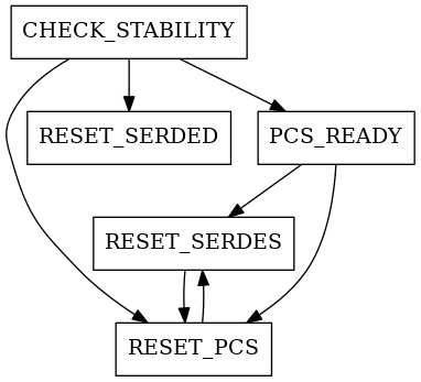
The module functionality is implemented using a state machine. A second process is used to check the stability of the pll lock.
The state machine has the following states: RESET_SERDES, RESET_PCS, CHECK_STABILITY and READY. At powerup or after asserting “rst”, or any serdes rst, the machine is in the RESET_SERDES state. The RESET_SERDES and RESET_PCS states last until the completion of the corresponding counters. The state of the link is monitored through the “lol_los” and “rx_err” variables. While the former is high, an internal lol_counter is incremented; if it finishes, the PLL is considered lost and the state goes back to SERDES_RST. While it is low, an internal lock_counter ticks instead, and if it finishes the state can change from CHECK_STABILITY to READY. In the CHECK_STABILITY state, if “rx_err” is high, meaning that a code violation or running disparity error has been detected, the error counter is incremented; if it reaches completion, the PCS is considered unstable and the state goes back to RESET_PCS