Ethernet IPV4 UDP formatter
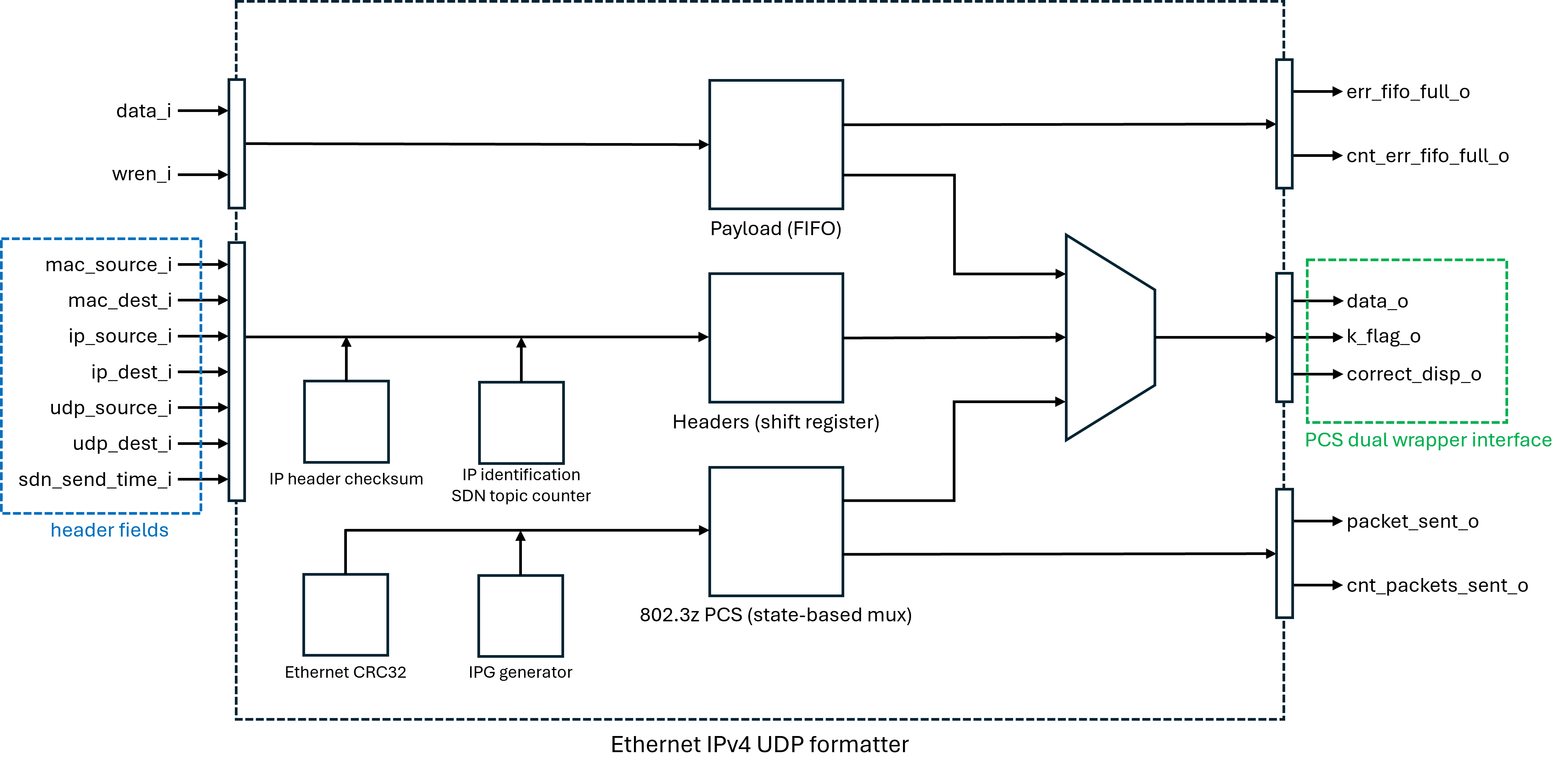
This module provides a VHDL-based Ethernet IPv4 UDP packet formatter for data transmission, interfacing with a FIFO input for data and a PCS interface for output. It constructs and transmits Ethernet frames with embedded IPv4, UDP and SDN headers, calculates checksums, and manages packet transmission states.
Generics
Name |
Description |
Type |
Default |
|---|---|---|---|
udp_payload_size_g |
Size of the UDP payload in bytes, without UDP and SDN headers (maximum of 8920 -> 890 HotRIO paquets) |
|
1424 |
sdn_topic_uid_g |
SDN topic unique identifier |
|
(x”00”, x”00”, x”00”, x”00”) |
sdn_topic_vers_g |
SDN topic version |
|
(x”00”, x”00”, x”00”, x”00”) |
Ports
Name |
Description |
Type |
|---|---|---|
clk_i |
TX clock of the PCS |
|
rstn_i |
Active-low, synchronous reset for the entire module |
|
data_i |
Input data vector for UDP payload bytes |
|
wren_i |
Internal FIFO write enable, set high to include |
|
mac_source_i |
Input source MAC address for Ethernet frame |
|
mac_dest_i |
Input destination MAC address for Ethernet frame |
|
ip_source_i |
Input source IPv4 address for the packet |
|
ip_dest_i |
Input destination IPv4 address for the packet |
|
udp_source_i |
Input source UDP port number |
|
udp_dest_i |
Input destination UDP port number |
|
sdn_send_time_i |
SDN header timestamp, to be provided by an external module if needed |
|
data_o |
Output data vector for PCS interface |
|
k_flag_o |
Output K flag signal for PCS interface |
|
correct_disp_o |
Control signal for the PCS to select the right disparity during an IPG |
|
packet_sent_o |
Pulses for one clock cycle when a packet transmission has ended (before the IPG) |
|
err_fifo_full_o |
Pulses high when a write is attempted while the internal FIFO is full |
|
cnt_packets_sent_o |
Output counter for packets successfully sent |
|
cnt_err_fifo_full_o |
Output counter for dropped payload bytes due to full internal FIFO |
|
Input Interface
This module assembles UDP payload bytes with MAC, IPv4, UDP and SDN header fields to produce valid 802.3z frames with fixed length, each containing a single non-fragmented UDP packet. An interpacket gap is generated between frames. The payload is provided by the user one byte at a time by setting data_i to the desired value while wren_i is held high. Bytes are appended to the payload and sent to the PCS interface in FIFO order.
To prevent data loss, the user shall ensure that the duty cycle of wren_i is less than (udp_payload_size_g)/(udp_payload_size_g + 117) over the time interval of each packet transmission. The following table shows three examples:
Payload size |
Write enable max duty cycle |
Notes |
|---|---|---|
10 |
7.8% |
Smallest supported payload |
1424 |
92.4% |
Largest non-fragmented packet with MTU 1500 |
8924 |
98.7% |
Largest supported payload |
The module will monitor the level of its internal buffer, ensuring it only begins transmission when the buffer contains enough data to complete a full packet, and providing an error signal on err_fifo_full_o if it runs out of memory. Buffer depth is automatically determined so that it always exceeds the sum of payload size and total header size, allowing the user to keep sending bytes continuously until the first payload is provided to the PCS.
Header fields are saved in a shift register near the start of packet transmission, when the start of frame delimiter (SFD) is sent. The desired changes to these ports must be applied no more than 12 clock cycles after the packet_sent_o pulse. The sdn_send_time_i timestamp should be calculated by a dedicated module, taking into account initial absolute time information provided from outside the FPGA. If this port is not assigned, it will default to zero. MAC and IPv4 addresses and IPv4 ports shall be provided in big endian format, while SDN header fields (topic UID, topic version and timestamp) shall be provided in little endian format.
PCS Interface
This module is compatible with the ecp5_dual_wrapper_8b PCS interface and consists of three main signals: an 8-bit data line, a k-character flag, and a disparity correction flag. The disparity correction flag pulses for one clock cycle upon entering the Interpacket Gap, enabling the PCS to reset disparity and begin the next frame with negative disparity.
Implementation Details
Packet Description
The main packet structure is the following:
Start of Packet (SOP)
A single 0xFB k-character
Preamble
Six 0x55 data bytes
Start of frame delimiter
A single 0xD5 data byte
MAC header (14 bytes)
IPv4 header (20 bytes)
UDP header (8 bytes)
SDN header (48 bytes)
Data
Frame check sequence, or FCS
4 bytes of CRC32 of the Ethernet packet content, from MAC header to the end of data
Interpacket gap (12 bytes minimum)
Made up of alternating 0xBC special characters and 0x50 data characters
MAC header
The MAC header consists of the following fields:
MAC destination, 6 bytes
MAC source, 6 bytes
Ether-type (set to 0x0800 for an IPv4 protocol), 2 bytes
IPV4 header
The IPV4 header structure is shown in the table below, 32 bits per row.
Version |
IHL |
Type |
Total Length |
|
Identification |
Flags |
Fragment Offset |
||
Time to Live |
Protocol |
Header Checksum |
||
Source IP Address |
||||
Destination IP Address |
||||
Table reference: RFC 791
Version (4 bits), set to 0x4 for IPv4
Internet Header Length (4 bits), set to 0x5 for a 20 bytes header (the minimum)
Type of service (1 byte), set to 0x0 for normal service
Total length (2 bytes), calculated during synthesis with the following formula: ipv4_length = 20 + 8 + 48 + udp_payload_size_g
Identification (2 bytes), a big endian 16-bit counter incremented at each packet sent
Flags (3 bits), set to 0x4 to “don’t Fragment”
Fragment offset (13 bits), not used, set to 0x000
Time to live (1 byte), set at 0xFF
Protocol (1 byte), set at 0x11 for the UDP protocol
The header checksum (2 bytes) is calculated dynamically. The explanation of this step is in the “Ipv4 checksum” section
Source IP Address (4 bytes), taken from the input port
Destination IP Address (4 bytes), taken from the input port
UDP header
Source Port |
Dest Port |
||
Length |
Checksum |
Source RFC 768
The UDP header is made up of 4 sections, each one of 16 bits:
Source port, taken from the input port
Destination port, taken from the input port
length, calculated with the following formula during synthesis: udp_length = 8 + udp_payload_size_g
Checksum, unused, set to 0x0000
SDN Header
This module will include a SDN header inside the UDP packet. The SDN header is made up of the following fields:
Header unique identifier (4 bytes)
Header version (4 bytes)
Header size (4 bytes)
Topic unique identifier (4 bytes)
Topic version (4 bytes)
Topic size (4 bytes)
Topic counter (8 bytes)
Packet send time (8 bytes)
Packet receive time (8 bytes)
Header UID, version and size are hardcoded to the values expected by the SDNv2.x core library. The topic UID and version can be set by the user at compile time through generics. Topic size and topic counter are generated inside this module, taking into account the requested payload length for the former, and incrementing the latter after each transmission operation. Finally, the packet receive timestamp is hardcoded to zero, as this module acts as a source of SDN data and does not receive any packets.
Main state machine
The main state machine is made up of 10 states. The states are selected one after the other in sequence.
IPG
During this state, the module sends an IDLE2 pattern to the PCS (0xBC 0x50), correcting running disparity by inserting an IDLE1 code group (0xBC 0xC5) if needed to guarantee that subsequent code groups are aligned on negative disparity boundaries.
The start of transmission of the Ethernet frame is triggered when three conditions are fulfilled:
The amount of data in the internal FIFO buffer is enough for an entire transmission, set by udp_payload_size_g.
At least 12 bytes of interpacket gap pattern have been sent.
A complete IDLE2 code group has just been sent.
PREAMBLE
In this state, the preamble of the Ethernet frame is sent: 0xFB 0x55 0x55 0x55 0x55 0x55 0x55 0xD5. Simultaneously, the module computes the checksum of the IPv4 header based on the IP addresses provided by the user at the beginning of the state.
Note that header fields are not yet registered in this state; this may result in checksum errors if the IP addresses are changed while calculation is in progress. To avoid these errors, ensure that input IP addresses are updated after no more than 12 cycles from assertion of
packet_sent_o. MAC, UDP and SDN fields may be updated later (up to 20 cycles afterpacket_sent_o), but it is advisable to change all header fields at the same time to prevent the potential transmission of inconsistent headers.HEADER
At the beginning of this state, all user-defined header fields are saved into a shift register, which proceeds to provide them one byte at a time at the PCS interface output. The internal FIFO read enable is asserted two cycles before the end of this process to account for Lattice ECP5 block memory latency, so that payload data is available at the beginning of the following state.
PAYLOAD
Payload bytes are fetched from the internal buffer and routed to the PCS interface output. Two cycles before the end of the process, the read enable is deasserted to compensate for its anticipated assertion in the previous state.
FINISH_CRC
During the header and payload states, data has been continuously intercepted by a CRC32 module, updating the value of the Ethernet Frame Check Sequence while the packet is being transmitted. This one-cycle state gives time for this module to finish calculation before sending the FCS.
No data is appended to the packet in this state, but transmission continues without any gaps as payload bytes travel to the module output through an intermediate register, while the frame check sequence, in the next state, is sent directly to the output.
FCS
As mentioned in the previous state, here the Frame Check Sequence is sent directly to the PCS interface output, bypassing the intermediate register to recover the delay needed to finish CRC calculation after extracting the last payload byte from the internal buffer.
The first character of the End of Packet Delimiter sequence, 0xFD, is also preloaded into the intermediate register, restoring normal data flow as soon as the state ends.
EPD
In this one-cycle state, the carrier extend special character 0xF7 is appended to the packet content, completing the alignment-independent part of the End of Packet Delimiter sequence started by the preloaded value from the previous state. The following state may be realign or ipg depending on the parity of the payload size.
When this state is reached, transmission of meaningful packet data has finished; thus,
packet_ready_opulses high and the packet counter, IPv4 identification number and SDN topic counter are incremented.REALIGN
If the payload size is odd, the 802.3z frame as generated above would end on an odd-aligned byte boundary. Since this would result in a PCS synchronization error on the receiver side, an additional carrier extend special character is appended to the data stream, so that the interpacket gap is guaranteed to begin on an even-aligned byte boundary, then the state machine restarts from the ipg state.
Ipv4 checksum
The IPv4 header checksum is computed for each packet while the main state machine is sending the frame preamble. The checksum calculation is performed by adding up the IPv4 header sections in 16-bits chunks. When an overflow occurs, the carry bit is added to the result. The checksum state machine does this only in the last step. It uses a 18 bit adder for all the intermediate steps, then it produces a 16-bit checksum by removing the three most significant bits of the sum, adding them to the remaining value. The calculation process takes 8 cycles, including state machine latency. At the end of the preamble state, the updated checksum is inserted in the IPv4 header, to be sent in the following state.
The checksum state machine contains the following states:
IDLE
The state machine waits for a start signal to begin calculation. The signal is internally provided by the main state machine at the end of the interpacket gap state.
SUM
In this state, one 16-bit chunk of the 160-bit IPv4 header is added to a 18-bit accumulator register at each cycle. The register is initially set to the sum of all constant fields of the header, so that calculation is only needed for the ones that can change: source and destination IP addresses and identification number.
CARRY_ADD
In this state, the final result is calculated by adding excess bits to the accumulator and inverting the result. The checksum is registered and made available to the main process, while the state returns to idle until a new packet transmission begins.
Ethernet CRC32
The Ethernet frame is closed with four bytes that correspond with the Frame Check Sequence. This value is a CRC32 calculation on the entire frame, including the payload and all the headers, but not the preamble. The vhdl code is based on an automatically generated CRC table, which combinationally provides an updated CRC given the previous CRC value and the current byte to be sent. At the end of the frame, the FCS is inverted and its endianness is swapped, according to the Gigabit Ethernet specification.
The CRC32 state machine contains the following states:
IDLE
The state machine waits for a start signal to begin calculation. This is internally provided by the main state machine at the end of the preamble state. The initial CRC value is set to 0xFFFFFFFF, resulting in the same outcome as would occur if the initial value were 0 but the first four bytes were inverted (which would be the specification requirement).
COMPUTE
In this state, the lookup table is used to update the content of the CRC register depending on the byte currently being sent to the PCS interface, which is acquired from the intermediate register between the main state machine and the output. This loop is interrupted upon reception of a stop signal from the main state machine, sent at the end of the payload state.
SEND
After the stop signal is received, the CRC register is rewired in a shift register configuration, so that it may produce the final value byte by byte on its output with the desired endianness. After transmission of the four CRC bytes, this state machine is restored to its initial conditions.
Internal FIFO buffer details
As mentioned in the Input Interface section, payload bytes are stored in a FIFO memory until they are in sufficient number to assemble and send a UDP datagram of the desired length. In vhdl, this component is defined as a single-clock FIFO IP core instance targeting Lattice ECP5UM-5G.
The specific module chosen for instantiation is determined at compile time based on the requested payload size. Each option has a different power of 2 as depth, from a minimum of 64 to a maximum of 16384. Whenever the chosen depth is 2048 or greater, dedicated block RAM resources are used to synthesize the module.
All FIFO options are 1-byte wide and feature synchronous reset, empty and full flags and a data counter indicating the amount of bytes currently stored in the module’s RAM. When attempting to transfer a value from the FIFO to a register, the effective latency of the read operation is 2 clock cycles, as the requested value will be visible at the output of the memory module shortly after the active edge that follows the request.
The module is wired in such a way that it is not possible to write the FIFO while full or to read it while empty, as long as single bit errors do not occur in the control logic of the UDP formatter. If the user attempts to write the FIFO while full, data will be ignored, an error flag will be raised for one clock cycle and an error counter will be incremented.