HotRIO slave
This module implements the core functionality of a HotRIO slave. It receives, decodes and retransmits a stream of HotRIO frames. If a packet inside the stream matches an address in the slave’s allocated range, the payload is exchanged: the received payload is made available in the FPGA and a new payload is inserted into the packet before retransmission.
The address range of the module is configurable by choosing its length at compilation time with a generic and its starting address at runtime with an 8-bit port. This simplifies the implementation of architectures where many slave nodes share the same firmware, making these nodes interchangeable as long as the user can control the starting address port from outside the firmware.
When the payload is exchanged, the address can be configured to be forwarded unchanged or to be edited by setting the MSB to 1. If the second option is chosen, the user should design the HotRIO master not to send any addresses where the MSB is already 1, halving the total number of available addresses from 256 to 128.
Aside from the main payload, the HotRIO slave supports a separate communication channel for sideband data (consisting of 6 bits per packet, included in the control byte). This data can be forwarded or exchanged independently of the payload, based on a sideband enable port. This module does not implement the sideband protocol, which should be controlled by a separate module by reading the RX sideband data and by driving the sideband enable and the TX sideband data.
This module uses an 8-bit interface with a PCS. The interface consists of an 8-bit bus plus a single bit that flags for k-characters.
On all the received packets, the parity bits are checked. If an error is detected, both parity bits are invalidated in the transmitted packet.
The module supports two clock architecture options: single-clock synchronous and CTC. The first is selected by setting ctc_g = false, the second by setting ctc_g = true.
If the logic is driven by a single clock, it must be synchronous with all input signals. The output signals produced will be synchronous to the same clock and may need phase alignment before reaching the 8b/10b encoder in the PCS. To avoid the need for external FIFOs, it is suggested to configure the PCS so that txi_clk and rxi_clk are driven by the same signal, which can then be used as clock for the HotRIO slave without any additional steps.
If CTC is used, the hotrio_ctc module performs a clock domain crossing from the clock used to receive the PCS data to the one used to transmit it. The hotrio_slave state machines are still fully included in a single clock domain, that of the transmitter. When operating in this mode, clk_rx_i must provide the receiver clock to the module.
Generics and ports
Generics
Name |
Description |
Type |
Default |
|---|---|---|---|
address_range_g | number of consecutive addresses belonging to this node |
|
|
exchange_delay_g | number of cycles needed by the user to prepare `tx_hotrio_payload_i` after receiving `new_request_s` |
|
|
reply_bit_g | if true, the msb is flipped in the tx address when the packet is a reply |
|
|
ctc_g | if true, clock tolerance compensation will be used to cross rx pcs data into the domain of the system clock |
|
|
Input signals
IN ports
Name |
Description |
Type |
|---|---|---|
clk_i | 125 mhz system clock. all outputs are in this clock domain and all inputs need to be, except for `rx_pcs_*` inputs if ctc_g = true |
|
clk_rx_i | rxi_clk of dcua. only needs to be provided if ctc_g = true |
|
rstn_i | active-low synchronous reset |
|
rx_pcs_data_i | byte from the pcs. if rxi_clk differs from txi_clk, use a fifo for cdc into `clk_i` domain |
|
rx_pcs_kchar_i | 8b/10b special character marker from the pcs. to be kept aligned with `rx_pcs_data_i` |
|
start_address_i | first address in the range belonging to this node |
|
tx_hotrio_payload_i | payload to be sent when the address matches this node |
|
sideband_en_i | if high `tx_hotrio_sideband_i` is sent on the sideband, otherwise `rx_hotrio_sideband_o` is forwarded |
|
tx_hotrio_sideband_i | sideband data to be sent when `sideband_en_i` is high |
|
Output signals
OUT ports
Name |
Description |
Type |
|---|---|---|
tx_pcs_data_o | byte to be sent to the pcs. can be directly connected with the pcs wrapper module |
|
tx_pcs_kchar_o | 8b/10b special character marker to be sent to the pcs. can be directly connected with the pcs wrapper module |
|
rx_hotrio_address_o | address of last received packet. available one cycle after reception |
|
rx_hotrio_payload_o | payload of last received packet. available one cycle after parity check |
|
rx_hotrio_sideband_o | sideband data in the last received packet. available one cycle after parity check |
|
time_o | 64-bit utc timestamp retrieved during the past four microseconds. valid when `pulse_4us_o` is high |
|
sync_o | high when the rx data stream is aligned with the "hotrio_slave_rx" state machine |
|
new_request_o | event: address received and made available on `rx_hotrio_address_o` |
|
new_packet_o | event: payload and sideband received and made available on `rx_hotrio_payload_o` and `rx_hotrio_sideband_o` |
|
packet_valid_o | event: parity check succeeded. can only happen simultaneously with `new_packet_o` |
|
pulse_4us_o | event: two-microsecond marker (2u) received |
|
pulse_1ms_o | event: millisecond marker (m) received |
|
pulse_1s_o | event: second marker (pps) received |
|
cnt_packets_received_o | number of packets received since last reset (including those forwarded to other nodes) |
|
cnt_err_kchar_o | number of wrong and/or wrongly positioned special characters received since last reset |
|
cnt_err_parity_o | number of parity errors detected since last reset |
|
cnt_err_ctc_o | number of ctc fifo overrun and/or underrun errors since last reset. leave open if ctc_g = false |
|
cnt_ctc_events_o | number of ctc activations (insertion and/or drops) since last reset. these are not errors. leave open if ctc_g = false |
|
Dependencies
Name |
Motivation |
|---|---|
Types definition and HotRIO constants. |
|
hotrio_utils |
Auxiliary module containing common logic used both in hotrio_master_rx and hotrio_slave |
Used to stretch 1-cycle pulses to a larger duration |
|
Used to detect edges and to cross clock domains in the CTC mechanism |
Implementation details
This module is implemented by means of two parallel state machines, one for the receiver and one for the transmitter. Between the two state machines, a queue of configurable length allows the introduction of a delay between the RX and TX functions, in case it is needed to give time to other firmware components to generate or select the payload to be sent based on the received address. When this user-defined delay is set to zero, the minimum latency of the HotRIO slave between RX and TX data amounts to 16 ns (two 125 MHz cycles).
State machines
The RX state machine consists on six states: SYNC, MARKER, PROTOCOL, MARKER_ADDRESS, PAYLOAD and CONTROL. The TX state machine only has five states, as it does not include the MARKER state.
After a reset, the RX state machine is in the SYNC state. In this state, it waits for a HOTRIO_4U marker and the sync_o output is kept low. All incoming data is forwarded to the TX state machine. When a valid HotRIO marker is received, the state machine transitions to the PROTOCOL state and sets sync_o to 1. When the marker reaches the TX state machine, it will cause a transition to the PROTOCOL state there as well.
The MARKER state is used when the RX state machine is synchronized with the incoming data. In this state, two things are checked: the status of the k-character flag and the incoming value itself. If the k-character flag is not high, it means that the received value is not a marker. In this case an error counter is incremented and the state machine goes back to the SYNC state. The incoming data is checked against the list of valid HotRIO markers; if the check succeeds, the corresponding output flag is raised following the scheme:
If comma character is received, no output flag is raised:
pulse_4us_o <= ‘0’
pulse_1ms_o <= ‘0’
pulse_1s_o <= ‘0’
If “4-microsecond” marker is received, only the first flag is raised:
pulse_4us_o <= ‘1’
pulse_1ms_o <= ‘0’
pulse_1s_o <= ‘0’
If the millisecond marker is received, the first two flags are raised as they overlap
pulse_4us_o <= ‘1’
pulse_1ms_o <= ‘1’
pulse_1s_o <= ‘0’
The same logic is followed if the second marker flag is received
pulse_4us_o <= ‘1’
pulse_1ms_o <= ‘1’
pulse_1s_o <= ‘1’
When pulse_4us_o is high, the 64-bit timestamp on time_o is valid and can be used by the rest of the firmware. The MARKER state lasts one cycle, followed by a transition to the PROTOCOL state.
In the following states (except for MARKER_ADDRESS), only data is expected and no k-characters. So in every state a check is added to verify that the k-character flag is low. If a k-character is detected, the k-character error counter is incremented and the state machine goes back to SYNC.
The PROTOCOL state lasts one cycle, during which RX data is shifted into the time_o output according to the HotRIO time communication mechanism. This state is also used for internal state machine operations in preparation for the next states.
In the MARKER_ADDRESS state the received byte is checked against the slave address range. If the check succeeds, the exchange flag is raised and communicated to the TX state machine. At the same time, the address is provided to the user and parity calculation of the received bytes begins. This state also accepts a HOTRIO_SKIP frame marker to support CTC adjustments; if this marker is detected, the state machine returns to the PROTOCL state instead of proceeding to PAYLOAD.
The PAYLOAD behavior in the TX state machine changes depending on the exchange flag. If the flag is not set, the incoming data is forwarded for the length of the HotRIO payload (defined in the globals as HOTRIO_PAYLOAD_SIZE). On the other hand, if the flag is set, the user-defined payload is sent to the pcs. Simultaneously, the RX state machine deserializes the received payload and makes it available to the user regardless of the exchange flag.
The CONTROL state checks the received parity bits. If this check is not successful, the transmitted parity bits are inverted to signal that an error occured. This is done even if the address was not previously recognized (If an error occured, it is possible that the address was corrupted). The rest of the bits of the control byte are considered sideband bits and forwarded or exchanged depending on sideband_en_i.
To handle state transitions out of the CONTROL state, a packet counter is incremented and compared to the constant HOTRIO_PACKETS_PER_FRAME. If all packets in the frame have been received, the state machine transitions to the MARKER state unless the next frame header is going to be controlled by CTC, otherwise it goes to the MARKER_ADDRESS state.
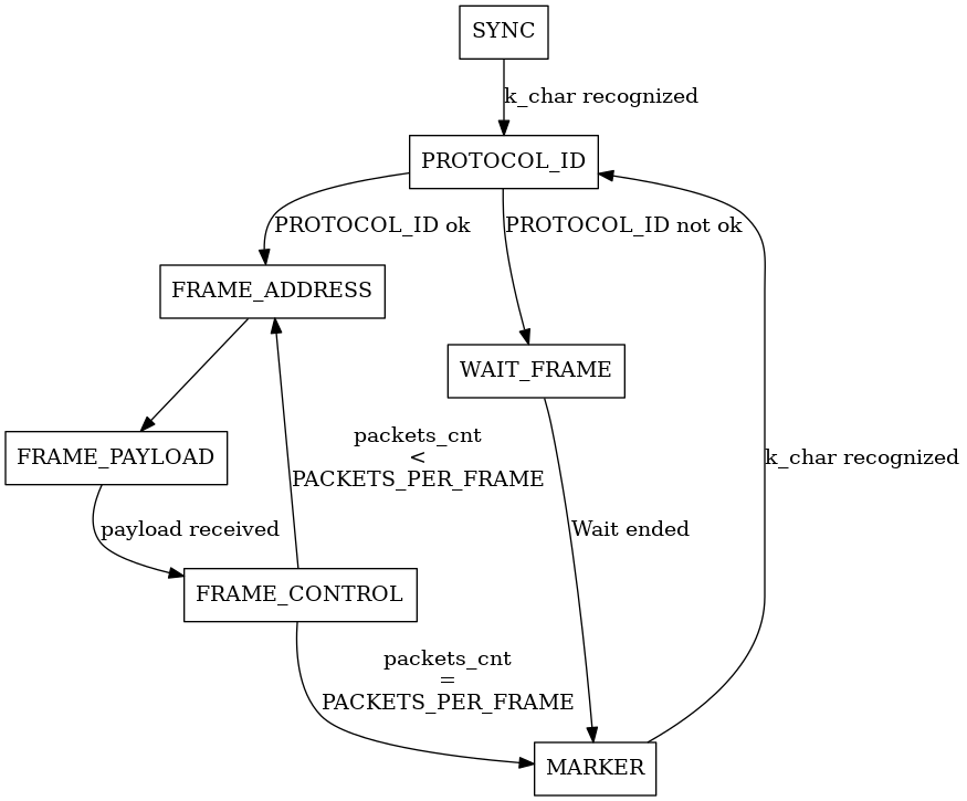
Note
To simplify the diagram, the connections in case of error are omitted. They connect every state to SYNC.