HotRIO master tx
This module generates the HotRIO packets as defined in the HotRIO protocol. The interface with the PCS is 8 bits.
This module must be clocked with the transmission clock provided by the PCS.
This module takes the address, payload and sideband fields of the HotRIO packet as inputs, using them to assemble a valid HotRIO data stream. The sent_o signal is pulsed high for one clock cycle when the packet to be sent has been latched internally.
As a HotRIO master, this module is responsible for the automatic generation of the proper sequence of frame markers to convey timing information and word alignment to the HotRIO chain.
The first marker produced is HOTRIO_S, which is then replicated once per second and can be used as a PPS signal in the downstream nodes. As such, if synchronization with an external PPS is needed it may be achieved by waiting for a rising edge of the external PPS signal before deasserting rstn_i.=
Detailed portlist
Input signals
IN ports
Name |
Description |
Type |
|---|---|---|
clk_i | must use the tx clock of the pcs |
|
rstn_i | active low synchronous reset |
|
hotrio_address_i | address of the next hotrio packet to be sent |
|
hotrio_payload_i | payload of the next hotrio packet to be sent |
|
hotrio_sideband_i | sideband bits of the next hotrio packet to be sent |
|
time_i | epoch time in nanoseconds |
|
Output signals
OUT ports
Name |
Description |
Type |
|---|---|---|
tx_pcs_data_o | ouput data to pcs |
|
tx_pcs_kchar_o | output k-character flag to pcs |
|
sent_o | pulse that goes high when a packet is sent. can be used to load the next packet on the hotrio inputs |
|
pulse_4us_o | pulse that goes high for one cycle every 4 microseconds |
|
pulse_1ms_o | pulse that goes high for one cycle every millisecond |
|
pulse_1s_o | pulse that goes high for one cycle every second |
|
Dependencies
Name |
Motivation |
|---|---|
Types definition and HotRIO constants |
Implementation details
This module is divided in two parts. The first is the state machine that generates the HotRIO packets. The second is the logic that generates the k-character flags, inserting the markers for the 4us, 1ms and 1s.
State machine
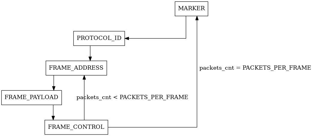
The state machine consists on four states: MARKER, PROTOCOL, DATA and CONTROL.
The state machine starts as soon as the reset signal is de-asserted.
The MARKER state is used to send the special characters to the PCS. The marker to be sent is selected by the marker generation part of this module. In this state, the k-character flag to the PCS is asserted to signal that the current byte is a special character.
The PROTOCOL state sends the protocol ID of the HotRIO protocol to the PCS. The protocol ID is defined in the globals package. During this state, the HotRIO inputs are latched and further changes are ignored until the state machine returns to this state. Epoch time is also transmitted during this state, in place of the protocol ID, when the frame marker is HOTRIO_K. Each 64-bit timestamp takes 10 frames to be transmitted, starting from the one that contains the timing flag (HOTRIO_4U, HOTRIO_M or HOTRIO_S).
The FRAME_ADDRESS state sends the address of the frame to the PCS.
In the DATA state address and payload are sent from the highest byte to the lowest. This is implemented with a simple shift register. A counter is used to keep track of the current byte being sent. The length of the payload is defined in the global package as HOTRIO_BYTES_IN_PAYLOAD.
The last state is the CONTROL. In this state, the control byte is sent to the PCS. A counter is used to keep track of the number of HotRIO packets to be sent in one frame. This is defined in the global package as PACKETS_PER_FRAME.
Marker generation
The implementation consists of three counters, one for the “4 microsecond” marker, on for the millisecond marker and one for the second marker. Two microseconds after the “4 microsecond” marker, the SKIP marker is sent. This notifies the following nodes that the current frame header can be dropped or duplicated if required by the Clock Tolerance Compensation (CTC) feature. When no other marker is selected, the HOTRIO_K marker is sent.
Parity bits generation
The parity bits are generated byte-by-byte during transmission, while the state machine is in the DATA state. The parity registers are reset in the other states to restart the computation at the beginning of the next packet.